Design Practice for
the Earthing System
of the 400 kV Gas Insulated Switching Station at Lavrion |
| |
G. J. Georgantzis
Public Power Corporation of Greece
Athens, Greece |
N. G. Gagaoudakis
Public Power Corporatioll of Greece
Athens. Greece |
TIL Connor
Siemens AG
Erlangen, Gennany |
|
| |
Abstrad: The paper presents the situation of the gas insulated 400
kV switching station at Lavion (If Public Power Corporation, Greece
as a part of a power station expansion project and gives details of
the" groued grid design.
Although the grotmd
grid design was carried out according to the American Standard IEEE
80 "Guide for safety in AC substation grounding", there
is a cross reference to the Gcnnaa Standard DIN VDE 0141 "Earthing
systems for power installations with rated voltages above t kV"
and the upcoming European Standard EN 50179 "Ereetion of electrical
power installations in systems with nominal voltages above I kV AC"
Besides the analysis of soil res.istivity wd the selection
of con- ductor Sizes, the detennination of fault current distribution
in Lie grounding system is a key step for the design of an effective
and economically feasible grounding system.
Finally,
the test procedure for verification of effectiveness of the earthing
system a6er completion of erection is given.
Keywords: Grounding SYSI.em design, GIlS insu!at.od swilchgear, Electromagnetic
compatibility |
| |
| l.introductton |
A closed type, metal enclosed, SF6 gas insulated 400
kV switching station, h.as been constructed and put in operation in
1998 at the area of Lavrion, to serve the new Lavrion 550 MW combined
cycle power plant with three gas and one steam rurbine units, as well
as the existing 300 MW old steam rurbine unit. One, already existing,
double circuit overhead line together with a new one single circuit
under construction transmit the power into metropolitan Athens area.
The s witching station with double busbar and nine 400 kV bays in
total is the first in that voltage level in Greece. A simplified layout
of the switching station is presented in Fig. 1.
Apart from the above units, there are also in operation at site one
ISO MWoil frred steam rurbine and one combined cycle unit with total
rating of 175 MW feeding power at 150 kV voltage level through an
air insulated 150 kV substation.
The limited dimensions
of the available space, almost 9000 m", as well as the great
industrial and sea pollution
problems at site, made the decision of constructing a compact closed
type gas insulated switchgear (GrS) substation obligatory.
GIS substalions offer a lot of advantages to utilities. They need
only small areas compared to outdoor conventional type switchgear.
they are independent from environmental conditions and can be considered
very reliable. Therefore, they are found in load and generation centres,
where the leve l· of short circuit capacity is high.
These
facts have an impact on the ground grid design. which has to guarantee
a safe substation with regard to step and touch voltages. Also the
interference with other systems nearby, like control systems, has
to be minimised in order to maintain operation under fault conditions
and to secure the quality of power.
All the above
mentioned units and the related switchgear are close together fonning
a llDified power complex of
1200 MW occupying an area of about 400 000 ml. Consequently tbe earthing
network of the new closed type GIS
substation could be assumed as-a part of the larger earthing nmvork
of the whole complex. Nevertheless for safety reasons, it is faced
as zn independent selfstanding network suitable to assure 310ne safe
operation and the protection of the staff in C3se of earth faults.
In this p3per description and details of the grounding
grid design both outdoor and indoor. together with the foreseeable
electromagnetic compatibility measures, are given. Although the design
was carried out according to the American Standard IEEE 80 "Guide
for safety in AC substation grounding" [1, 2], there is a cross
reference to the Gennan Stand.lJd DIN VDE OJ41 "Earthmg systems
for power installation with rated voltages above I kV" [3] and
the upcoming European Standard EV 50179 "Erection of electrical
power installations in systems with nominal voltages above I kV AC"
[4].
The paper especially discusses the detennination
ofsoil.resistivity, the selection of material and cross section of
ground conductors. the tolerable touch and step voltages, the expected
.ground potential rise, the design details and the rest procedure
for verification of effectiveness of the earthing system after completion
of the erection. |
 |
| |
| II. Determination of Soil Resistivity |
In order to design the earthing system afthe substation.
the resistance to earth has to be calculated in advance. This value
depends on two parameters whictl can hardly be influenced by the designer.
The area covered by the installation and the specific soil resistivity
beneath, As the specific soil resistivity varies considerably with
type and structure of soil the reliable detennination of effective
soil resistivity is essential for a safe aJld ec()Tlomic design,
In order to detennine me soil sIDlcrure also in deeper
layers, the Wenner method, which uses 4 electrodes at the surface
to measure soil resistivity also in larger depth; has proved to be
a useful tool. The resulting diagram of apparent soil resistivity
is the basis to identify top and bottom layer resistivity as well
as top layer thlclcness.
For the Lavrion site out
of 4 sequences with spacing up to 30 m the decisive parameters were
taken,
Pr = 160 Ω ·m top layer resistivity
PB
= 60 Ω ·m bottom Jayer resistivity
h = 13 m top layer
thickness
Considering, the area of the intercoonecled earth grid of substation
and power station of more than 160000 ㎡ , the
effective equivalent resistivity for a homogenous soil comes to 68
Ω ·m |
| |
| Ill. Thermal Design |
The task of earthing conductors is to carry the line
to ground fault current from the fau lted component and distrib·
ute it to the buried earth electrodes. Tne siring has to be done in
3. way that no damage or melting will occur even in case of auto reclosure
or subsequent faults in short sequence.
The design for the 400 kV equipment was based on the following parameters:
For copper conductors this results in a required minimum
cross section of 220 rnm2? For earthing conduc tors of equipment which
is connected at least twice or for the meshed part of the grid a split
up of current can be considered. In this case a copper cross section
of 150 mm1 is sufficient. |
| |
| IV. Tolerable Touch and Step Voltages |
In case of a line to ground fault a person in or outside
the substation can be subjected to a potential dirference between
hand and feet, hand and hand or foot and foot. This potential difference
will lead to a cumnt through the body, which. has to be limited to
a safe level not causing ventricular fibrillation of the hew. Based
on the current limit found by Dalziel, the IEEE standard 80 gives
fonnu las to detennine tolerable touch and step voltages under consideration
of body and feet resistances as well as fault duration:
|
| |
| V. Determination of Expected Ground Potential Rise |
In case of a line to ground fault in the substation
area the fault current will return on different path. Part of the
fault
current will flow through me interconnecred earth grid to the grounded
neutrals of the generator transfonners. Another part will return due
to inductive coupling through the ground wires of the outgoing overhead
lines. The rest will be split up according to the ratio of resistances
between substation earth grid and power station earth grid.
The resistance to earth of an earth grid lies in between the value
of a solid plate and a single earth electrode surroWlding the area.
The fonnu la according to IEEE 80 considers the actual dens ity of
the meshed grid by taking into account the length of the buried conductors. |
 |
 |
 |
| |
| VI. Check of Design regarding Touch and Step VOltages |
| Based on the expected ground potentlaI rise it was decided
to install in the substation area not covered by fo undations a buried
earth grid wilh rectangular meshes having a maximum mesh width of
10 m. The calculation of mesh voltage according to the formulas of
IEEE SO gave Umeln co 422 V. As this mesh voltage is smaller than
the tolerable touch voltage, the design requirements with respect
to touch voltages are fulfi lled. The analysis of step voltages gave
Ustep = 278 V, which also satisfies the requirements of tolerable
step vo.1tages. |
| |
| VIl. Details of Earthing System Design |
The main oomponents of the earthing system are the meshed
and buried outdoor earthing grid, the foundation
ground electrode of the buildings and the indoor earthing system.
The structure is given in Fig 3.
In order to fonn
a foundation ground electrode steel bars are welded together and embedded
in the concrete of the
lowest floor. The steel bars are wrapped to the reinforcement rnats
and have risers to the indoor earthing system.
A
main earthing conductor which runs along the wall is the backbone
of the indoor earthing system. All components which can carry the
fault current are connected via earthing conductors to the main earthing
conductor at least twice.
There are several connections to the outdoor earthing system,
High voltage gas insulated switchgear causes transient
potential differences when isolators are switched. In order to prevent
arcing between grounded metal strucrures and to reduce interference
on secondary equipment, additional measures with respect to electromagnetic
compatibility are considered, |
 |
Equipotential bonding for high frequencies
Enclosure
earthing in a low inductive manner
Secondary wiring
~ith suitable screens
Rooms of the control building
with sensitive equipment are shielded in order to minimise interference
from electramagnetic fields radiated from 400 kV outdoor bushings
during isolator switching.
There are earth wires between
the metal support of the surge arrestors and the 400 kV bushings of
the outgoing
overhead lines,
Each building is surrounded by a·
potential control electrode in 1 m distance to the building. The lightning
protection system is interconnected with the earthing system. |
| |
| VIII. Current Injection Test |
In order to check the effectiveness of the earthing
system it is intended to carry out a current injection test after
completion of the erection. For this purpose an outgoing overhead
line will be short circuited and grounded in about 6 km distance.
In the substation a single phase current source will be connected
between· the tbiee phase conductors of the overhead line and the substation
earth grid (Fig. 4). The test current will be about ISO A. During
the test the following data are recorded
Ground potential
rise
Touch voltages and transferred potential
Step voltages
Potential differences within
the earth grid
Zero sequence impedance of test line
|
 |
| |
| IX. Design Procedure according to German Standard |
The DIN VDE standard 0141 requires a design
of the earthing system with respect to thermal and mechanical
stresses., as well as a design to meet touch voltage requirements.
While the thermal design gives almost the same results as IEEE 80,
the approach to meet touch voltage requirements is different.
It is presumed that the calculation of ground potential
rise is far more accurate and easy to handle than the theoretical
determination of touch voltages.
The tolerable touch
voltage can be taken from a diagram giving the tolerable touch voltage
as a function offau!t duration. This diagram is based on the body
current limits given in lEe 479 [5]. In VDE it is stated that the
correct operation of protection and circuit breakers can be presupposed.
As the tolerable touch voltage according to VDE is not considering
feet resistances, the value is smaller than the IEEE value.
There is no step voltage limit given in VDE 0141.
|
| |
| x. Earthing requirements of upcoming European Standard |
With the upcoming European Standard EN 50179 the requirements
for earth grid design of a substation will be part
of a general standard for the erection of high voltage installations.
The thennal design will be similar to the procedure known from
IEEE and VDE.
The design with respect to touch voltages
is based on the VDE approach. There is a diagram giving the tolerable
touch voltages in dependence of fault duration. Additional curves
give limits for touch voltages under consideration. of foot and shoe
resistances. As there is no formula to calculate touch voltages there
are certain circumstances listed under which the earth grid can be
considered as sufficient to keep touch voltage limits.
|
| |
| XI. Sununary |
The careful design of an earthing system for a substation
is necessary to assure not only the protection of the staff, but also
the safe operation, in case of eanh faults. Substations with gas insulated
Switchgear need even more efforts because ofthetr limited dimensions.
The closed type, metal enclosed, SF 6 gas insulated 400
kV switching station at Lamon, the first in that voltage level in
Greece, has been constructed and put·into operation in -1998 .
As some of the main components of the earthing system
are integrated into the civil works, it was essential to design me
earthing system at the very beg;irming of the project.
Details of the design, which was carried out according to the American
Standard IEEE 80, arc given in the paper. As a cross reference the
requirements of the German Standard DIN VDE 0141 and the upcom ing
European Standard EN 50179 are given. The aspect of electromagnetic
compatibility in the surrounding of the GIS was considered.
Finally
Ihe test procedure for verification of the effective-ness of earthing
system after compl etion of erection is given. |
| |
| XII. References |
[1] ANSUlEEE Std 80-1986 "Guide for Saf~ in AC Substation Grounding"
(2] ANS1JIEEE Std 81-1983 "Guide for Measuring Earth Resistivity,
Ground Impedance and Earth Surface
Potentials of a Ground System"
[3] DIN VDE 014 1-1989 "Erdungen fur Starksttomanlagen mit Nennspannungen
Ober 1 kV"
[4] prEN 50179-1996 "Erection of electrical power instaUations
in systems with nominal voltages above I kV AC"
[5] LEe 479-1/1 984 "Effects of current passing through the human
oody" |
| |
| XIII. Biographies |
 |
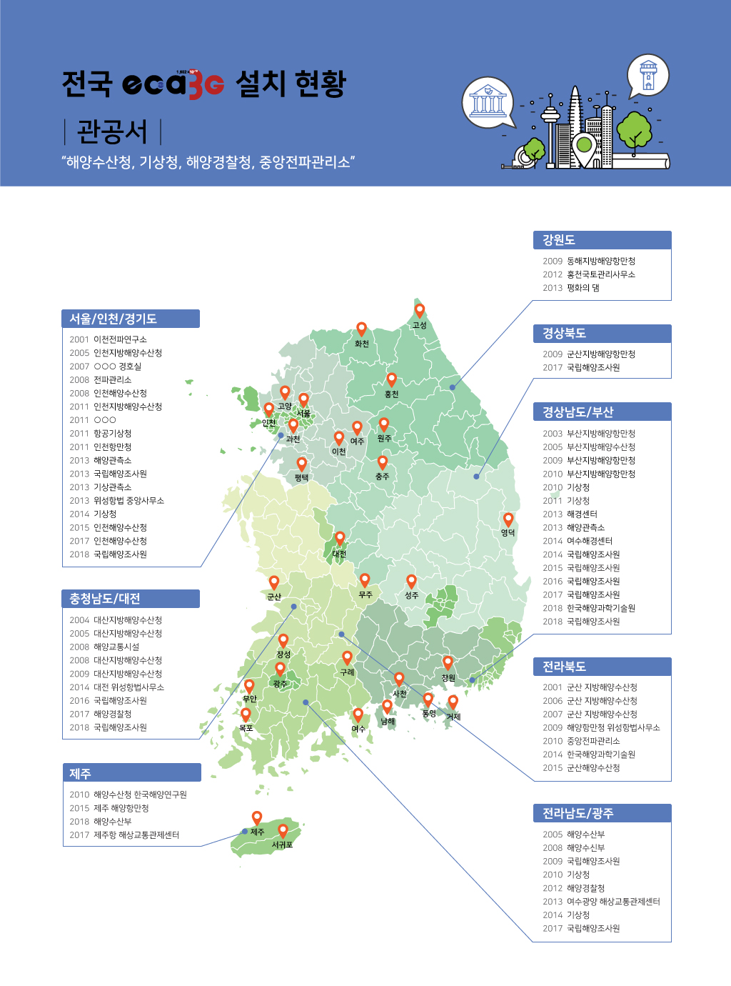
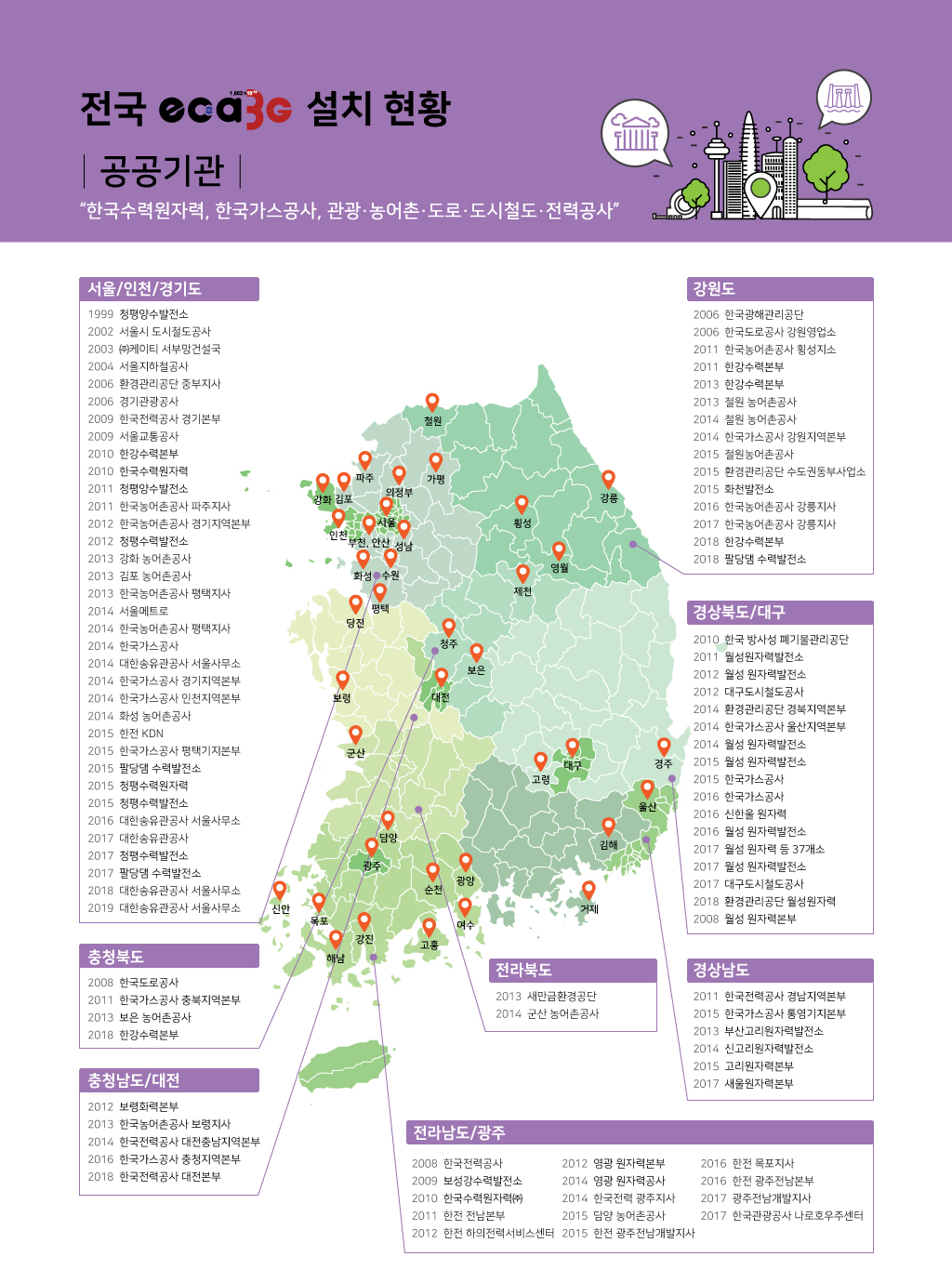
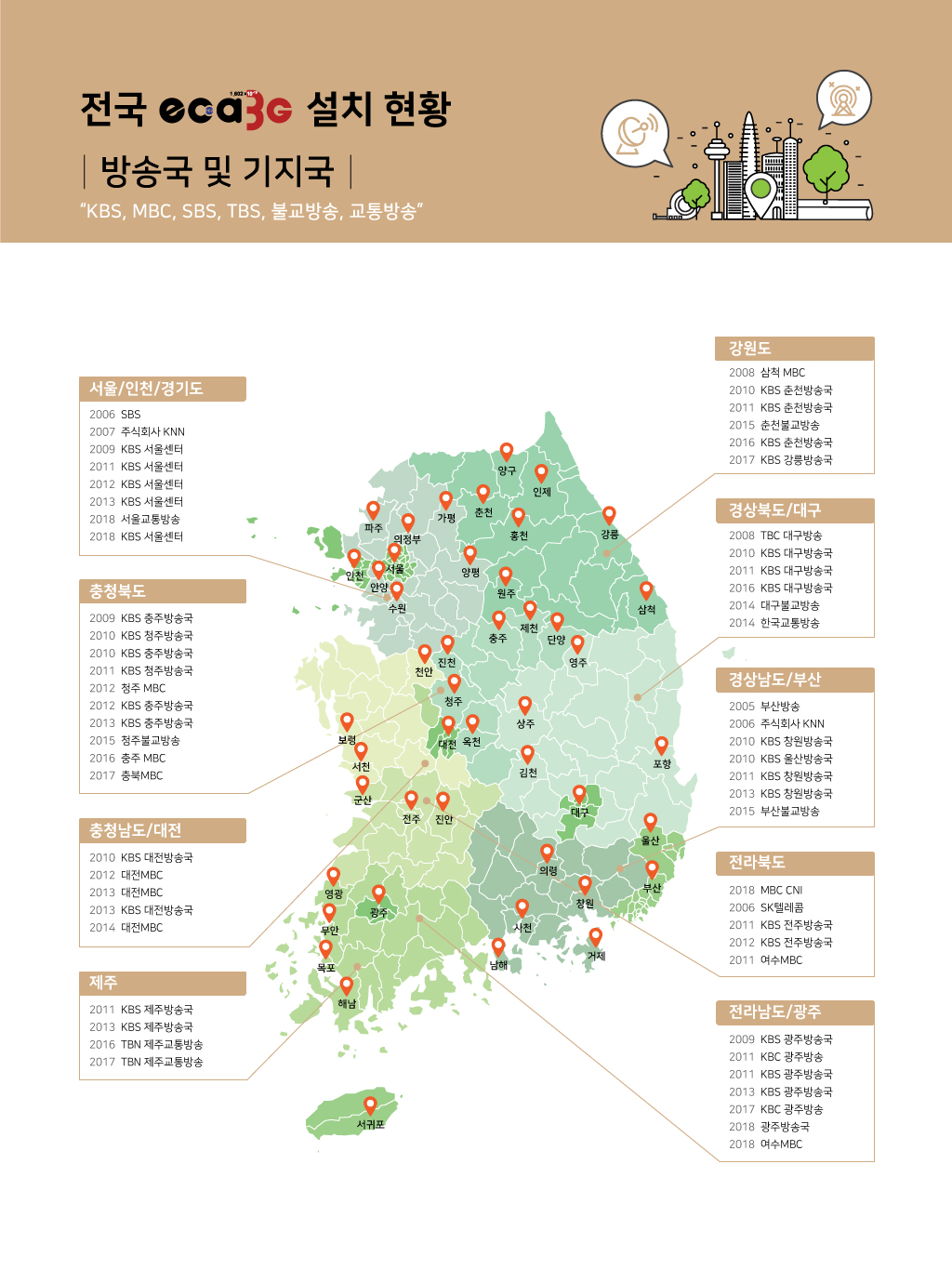
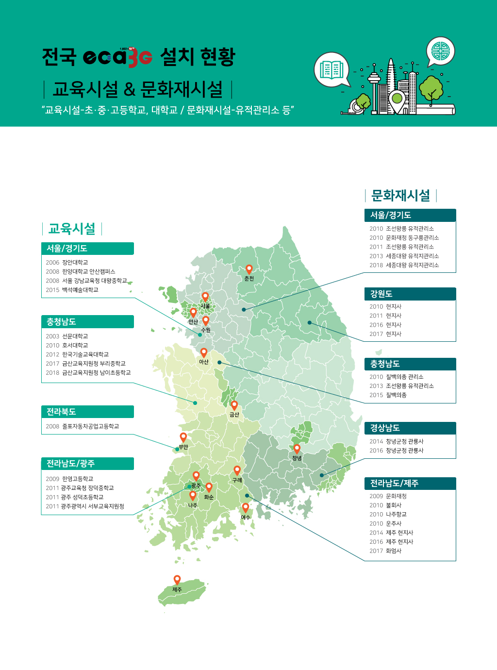
 eca3G 성능인증(EPC)획득
 낙뢰방호 현장설계모음
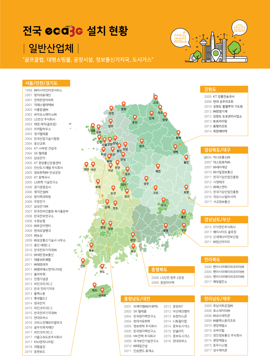
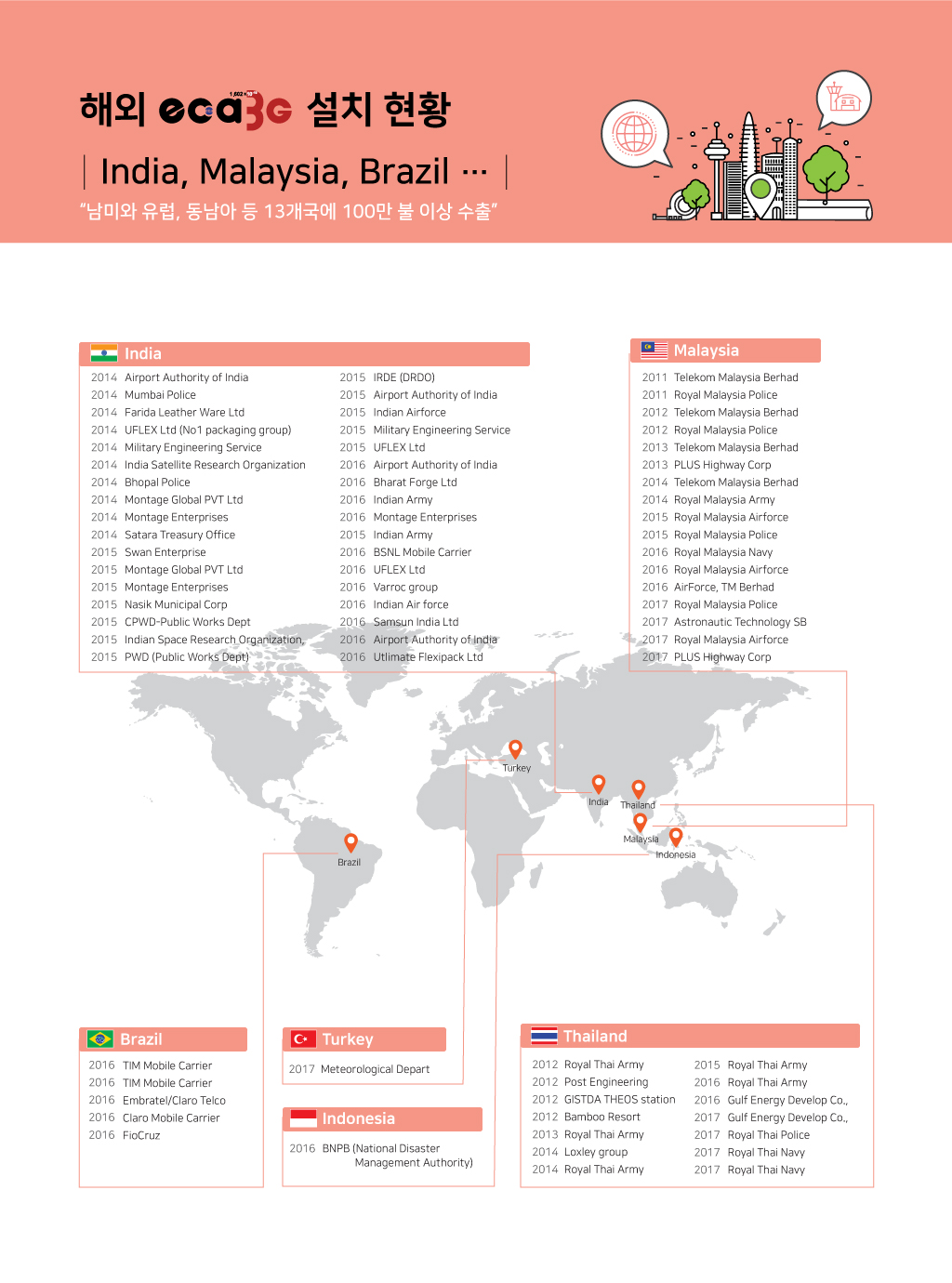
 주요 실적
주요 실적
 낙뢰 피해대책


 139
139