 |
| TRANSIENT IMPEDANCE
OF GROUNDING RODS |
| |
| I. F. Gonas |
F. V. Topalis |
1. A Stathopulos |
National Technical University of
Athens
Depanment of Electrical and Computer Enginee ring, High Voltage
Laboratory |
|
| |
Abstract: The aim of this paper is the correlation of the transient
impedance and its parameters ,vith the statiollary resistance of
simple grounding systems. Impulse current tests of -the standard
form-Si20 IJ.s were performed on several types of equilateral triangles
and single driven rods of different lengths. The injected current
in the grounding system and the developed potential were recorded,
resulting in the determination of the time "ariation of the
transient impedance. Further mathematical analysis of the experimental
results led to simple linear relations between the parameter of
transient impedance and the stationary resistance. The results provide
useful information for the design of a grounding system a nd the
measures for the protection of instal lations from lightning strokes.
Key words: Grounding system, transient impedance, stationary resistance. |
| |
| 1. Introduction |
The grounding systems serve multiple purposes. Not only the) do
insure a reference potential point for the electric and electronic
devices but also provide a low reSIstance path for fault currents
into the earth. Such fault currents Call arise either from internal
sources or from ex.ternal ones e.g. by lightning strokes and industrially-generated
static electricity. The
resistance of grounding systems has an essential influence on the
protection of the grounded system. Grounding systems can consist of
one or more vertical or horizontal ground rods, three or more vertical
ground rods connected to each other and two or three·dimensional grids
from metal rods and foundation grounding systems.
The behaviour of the grounding system under lightning determines the
degree of protection provided. This makes obvious the purpose of analysis
procedures predicting the trans ient response of grounding systems.
If an equivalent circuit approach is adopted these procedure can be
implemented in a simulation model [1-7].
The specific value of impulse impedance which is of main interest
is tlle one corresponding to the beginning of the steep ascent for
the wave-froot. The resu lts reveal its value to be quite higher than
the stationary value of its ground
resistance and reduces to this latter value [3, 5].
The work presented in this paper refers to the prob lem of transient
analysis of practical grounding systems cons isting of grounding rods
under impulse lightning currents. |
| |
| 2. Fundamentals |
The driven rod is one of the simplest and most economical form of
electrodes. The stationary resislance R of a driven rod is given by
the following fonnula [7]:
 |
When the electrode voltage changes with time, there will be a conductive
current in add ition to a capacitive current. The equivalent circuit
of a driven rod under impulse current is shovm in Fig. 1. The resistance
R of the rod is given by the Eq. (1) and the inductance L of such
a rod is equal to [7, 8]:
 |
where:
Z1 , is the maximum value of the ratio of impulse voltage to impulse
current. Z2 is the ratio of tho maximum value of voltage to the respecti
ve value of current when voltage reaches its maximum, Z3 is the ratio
of maximum value of voltage to the maximum value of current and Z4
is the ratio of voltage when current reaches its maximum to the maximum
value of cu rrent.
It is obvious:
ZI >Z2 > Z3 >Z4>R (9)
|
A lightning discha rge affects the resistance of a grounding system
in two ways. The current is up to 100 kA or more and has a much higher
frequency spectrum than the stationary case.
The transient impedance becomes greater as:
● the inducti vity of the wire and of the connection becomes grenter
● the high value of current can dry the ground,
● the high frequency spectrum shortens the electrical length of long
grounding wires
● the skin effect rises the resistance and the inductivity of wires
due to the value of the frequency. |
| The transient impedance becomes smaller as the electrical field
strength on the surfuce of grounding system can reach values where
predischarges in the ground start: these discharges can lead to ground
ionisation that destroy layers with high resistance [4]. |
| |
| 3. Experimental apparatus and test techniques |
The layouts of grounding system (Fig. 3) werle tested experimental
ly under impul se lightning current of waveshapc 8/20 μs The maximum
value of the current vas varying up to 3 kA The first grounding layout
was a single driven rod and the second one was an equilateral triangle
with three vertical rods. Cooper rods with diameter 20 mm were used,
The measured value
of the earth res istivity was found to be equal to 30 .Ω . m. The
wavetbnns of the impulse cunent and of the potential of grounding
system were recorded directly by a data acquisition system controlled
by a personal computer, with
measuring bandwidth of 20 MHz.
|
| |
| 4. Test results |
The measurements values of peak volrage. peak current
and impedance often different grounding layouts are presented in Table
1,
|
| In these figures, the test results for the grou nding system of
a driven rod wi th diameter 20mm and length 75cm arc presented. The
waveforms of the injected current is Show in Fig. 4 The measured potential
with reference to the ideal earth is shovm in Fig 5. The transient
impedance of the grounding system under this stress is the one of
Fig. 6. |
|
| |
| 5. Conclusions |
The perfonned measurements, show that the transienr impedance reaches
its maximum value very fast (fraction of microsecond) and consecutively
is reduced (0 rhe value of the stationary resistance. the one corresponding
to
the beginning of the steep ascent for the wave~ front. The results
reveal the value of the transient impedance to b ~ quite higher than
the stationary resistance. The determined analytical relations between
the parameters of the transient impedance and the stationar) resistance
anow the limitation or even elimination of time and money consuming
experiments. It will also facilitate the optimisation of any planned
grounding system. The computer aided
optimisation of grounding systems is very useful, since the improvement
of them after their installation is a difficult task and sometimes
not possible, |
| |
| References. |
[1] SufIis, S.A., Gonos, l.F :. Topahs, F.Y. and Stathoplilos LA.:
Transient behaviour of a horizontal grounding rod under impulse
current", Recent Advances in Circuits and Systems, Word Scientific
Publishing Company, Singapore, 1998, pp. 61 ~ 64,
[2]Suflis, S.A., Gonos, I. F., Topaiis, F. Y. and Stathopulos I. A.:
"Transient behaviour of a horizontal grounding rod under impulse
current", 2nd International Conference on Circuits, Systems
and Computers (lMACSCSC"
98), October 1998, Piraeus, Greece, pp. 289·292
[3] Gonos, l.F., Antoniou, M.K., Topalis, F.V. and Stathopulos I.
A. : "Behaviour of a grounding system under impulse lighming
current", 6lh International Conference and Exllibition on Optimisation
of Electrical and
Electronic Equipment (OPTIM 98), May 1998, Brasov, Romania, pp. 171
~ 174.
[4] Bogensperger, H.J., Frei, J. and Pack, S.: Resistance of grounding
systems, stationary and transient behaviour", 9th lntematiom
S}mposium on High Voltage Engineering, August! 995, Graz, Austria,
pp. 6715-1-4.
[5] Verma, R. and Mukhedkar D .. "Impulse impedance of buried
ground wire", iEEE Trans. on Power ApparatUs and Systems, [980,
PAS·99 (5) pp. 2003·2007.
[6]Meliopoulos, P.A. and Moharam, G.M. "Transient Analysis of
Grounding S}stems", iEEE Trans. on Power Appdratus and ,Iystems,
[983, PAS·[02 (2) pp .389·397.
[7] Kalifa, M.; "High Vorlage Engineeri ng, Theory and Praclice",
Dekker, USA, 1990, pp.3 31·356.
[8] Gupta, R.B., and Thapar, B, "Impulse Impedance of Grounding
Grids", IEEE Tran s. on Power Apparatu~ and Systems, 1980. PAS,99
(6) pp. 2357·2362.
Address of Authors
National Teclmica! University of Athens
Dept. of Electrical and Computer Engineering
42, Patission Str., GR~1068 2 Athens, Greece
Tel.: + 30 ~1- 7723539, 7723627, 7723582 .
Fax.: +30· 1· 7723628. 7723504
Email .: igonos@soft lab:ece.ntua.gr
topalis@Softlab.ece.ntua.gr
stathop@:power. ece.nlua.gr |
|
|
|
|
|
 eca3G 성능인증(EPC)획득
 낙뢰방호 현장설계모음
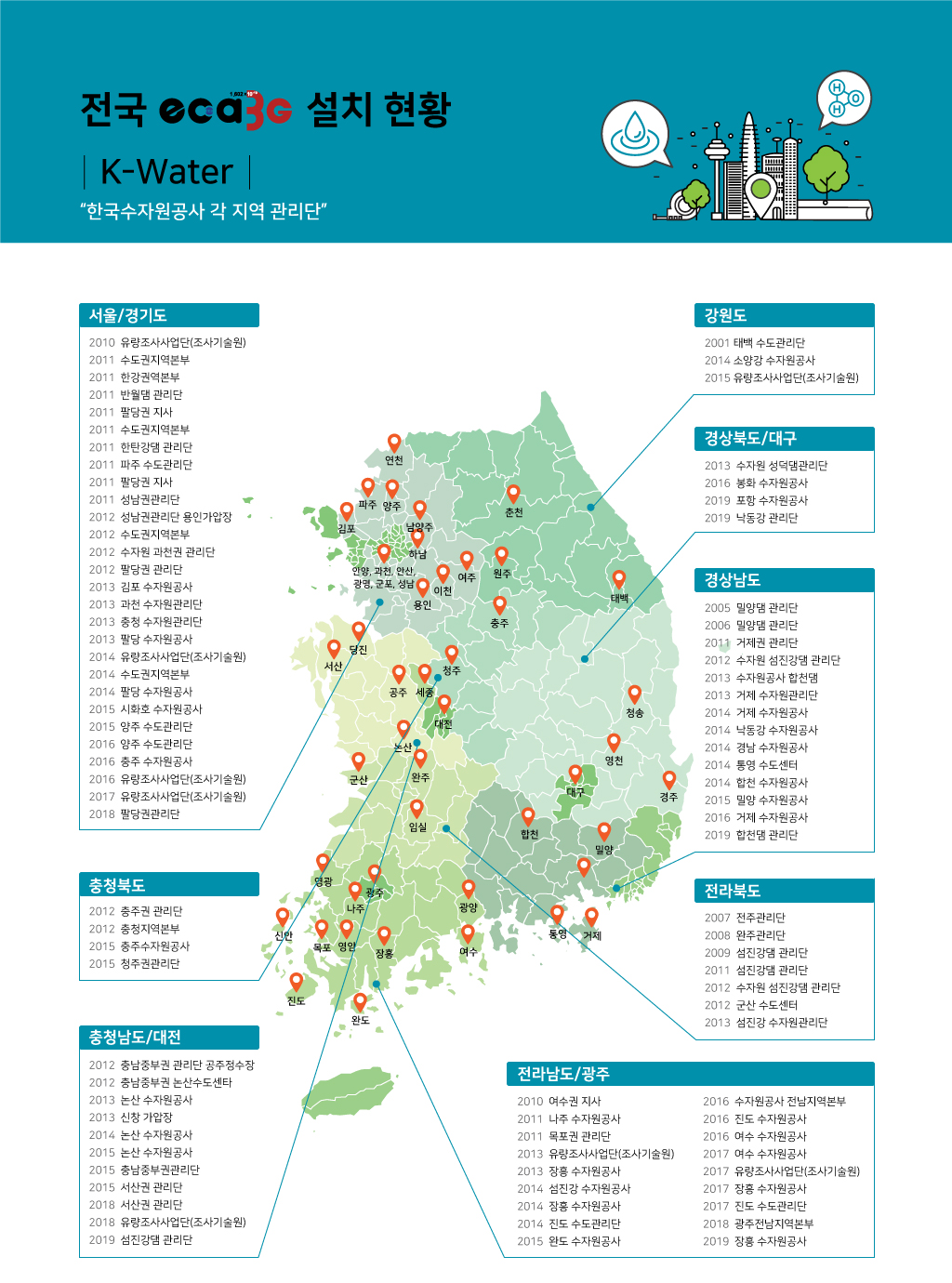
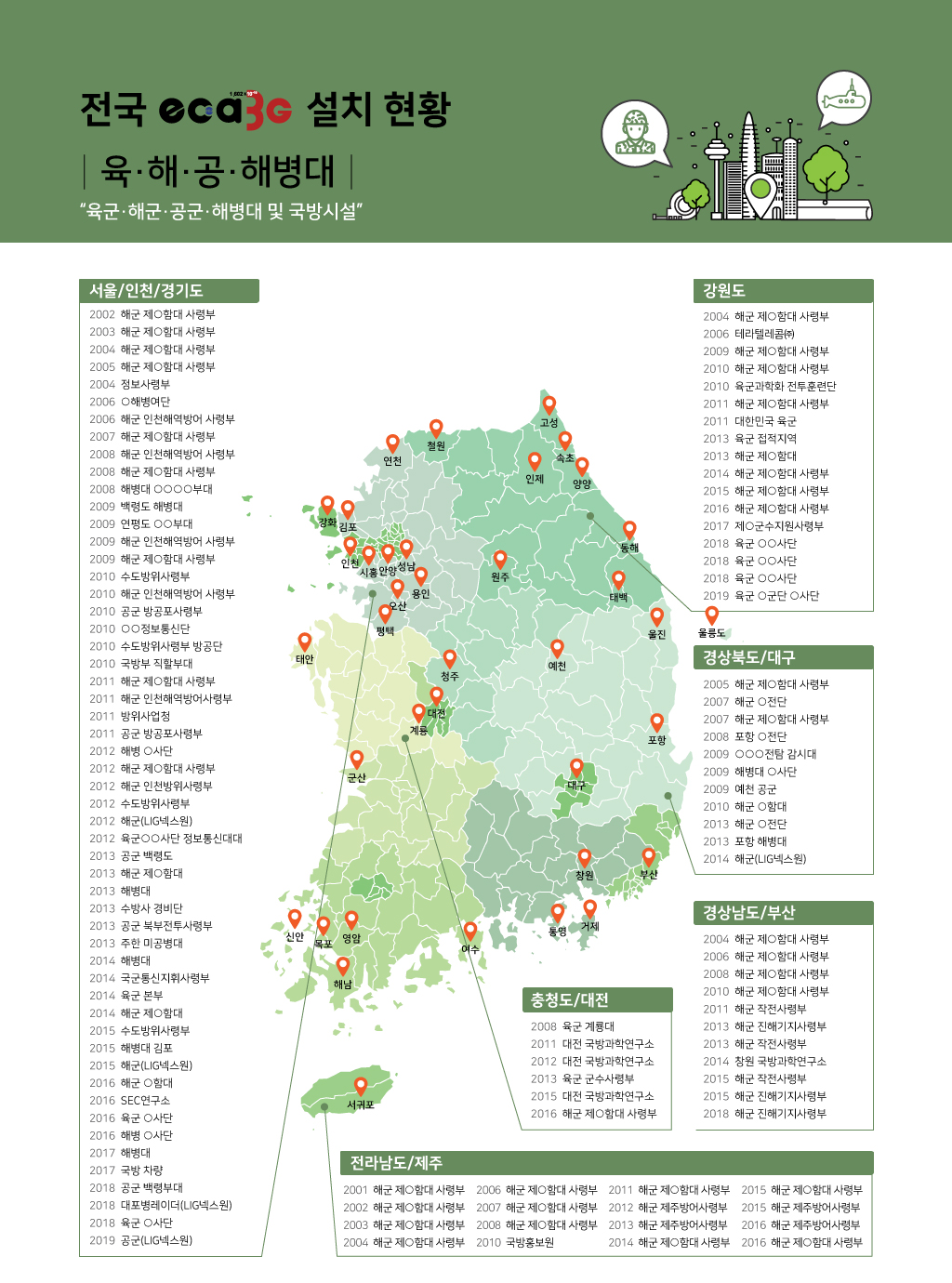
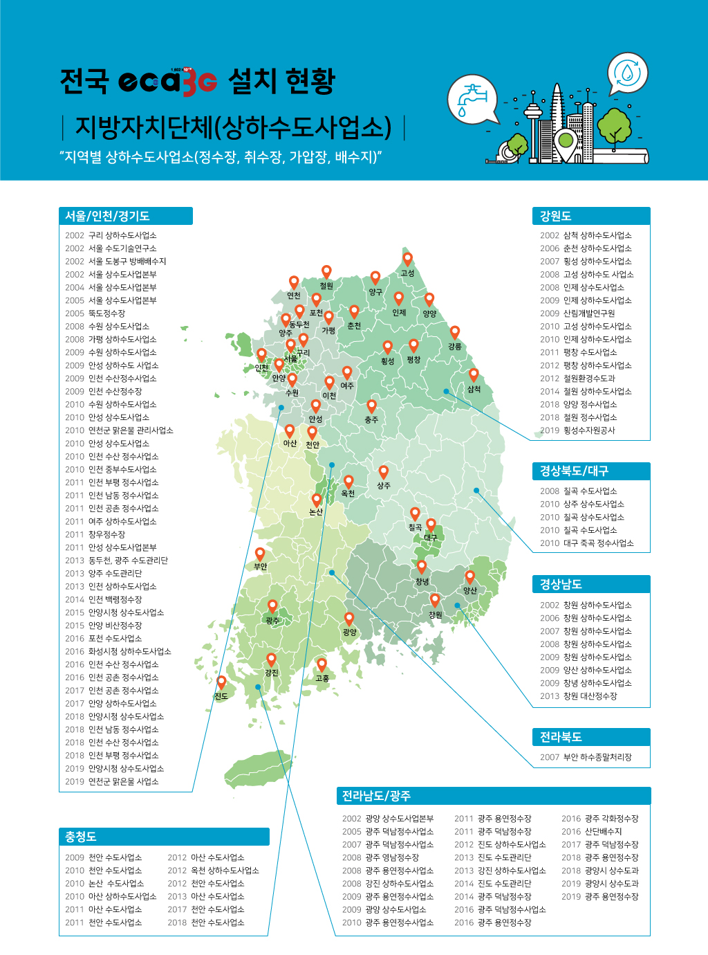
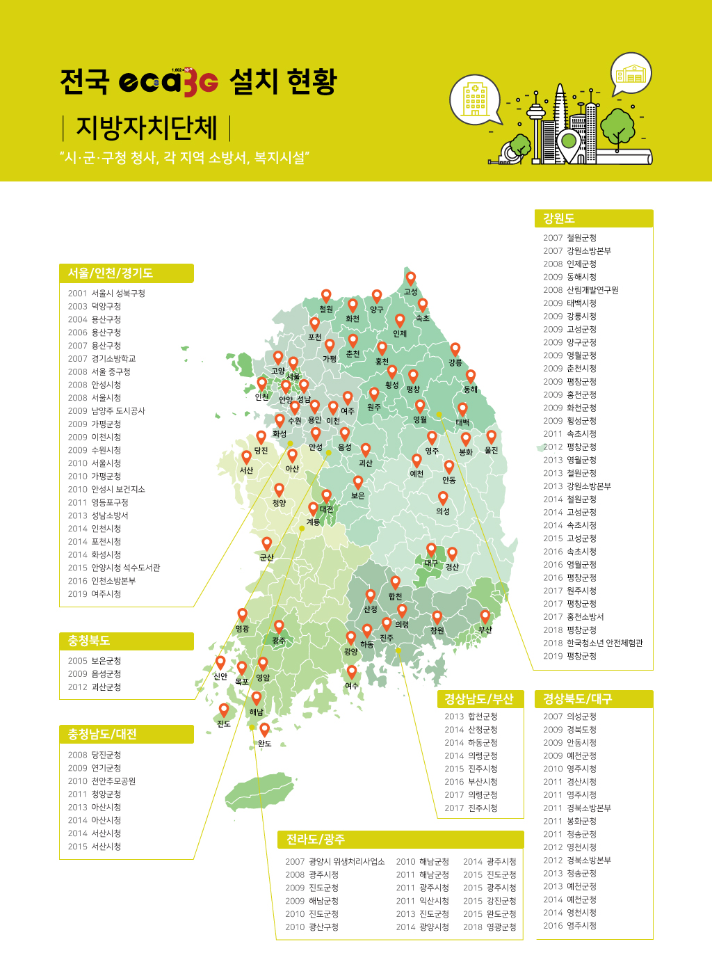
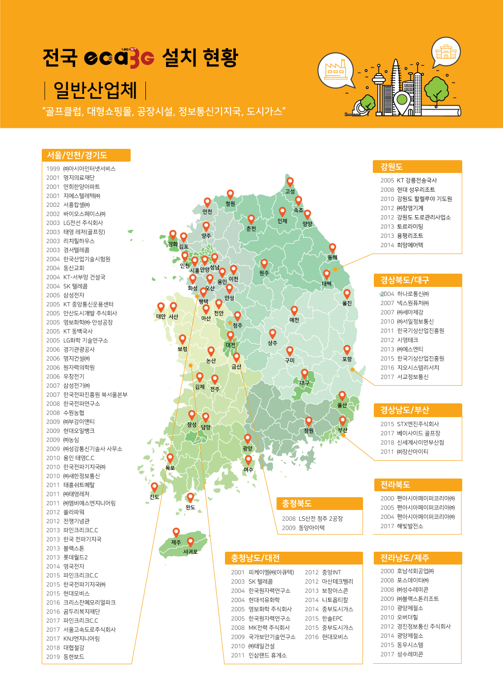
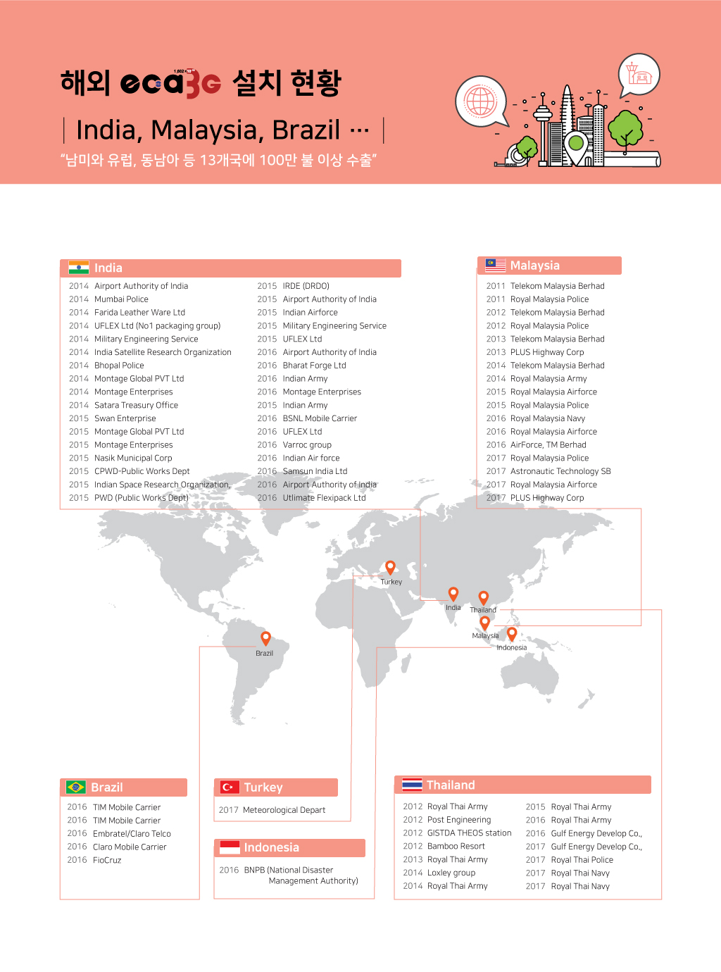
 주요 실적
주요 실적
 낙뢰 피해대책


 139
139


