 |
| high availability
electrical power distribution |
| |
| 4. solutions for increasing availability |
The minimal basic architecture (cf. fig. 4) studied
above, produces a maximum unavailability rate of about
5 h per year (i.e. 6.10-4) with minimal back-up battery autonomy
of 10 mn, and preventive and corrective
maintenance requiring no assistance (cf. fig. 12).
The distribution of failure probabilities is expressed in terms
of minutes of ≪failure≫ per year. If the targeted
unavailability is less than 1 h/y (10-4) on the feeder backed up
by the UPS, improvements need to be made to the
basic architecture and/or components.
This is possible by:
■ ensuring key component reliability;
■ choosing the appropriate technologies and techniques;
■ having a fine division of operation in the aim of:
□ enabling stepped operation (modularity),
□ ensuring operation by only the components required;
■ redundancy. |
| knowing the level of component reliability |
The reliability of a system (mechanical, electrical
and electronic) is its aptitude to perform a required function, under
given conditions, during a given period of time; it is the
probability of system survival (cf. Cahier Technique n° 144
≪Introduction to dependability design≫).
As a result, the various mechanical, electrical and electronic constituents
must be chosen according to quality
and reliability levels, taking into account the thermal, climatic
and mechanical environments, this being particularly
true for components that bear substantial ≪weight≫ on unavailability.
Debugging can be employed to bring out latent defects that are liable
to appear in the operating environment,
without affecting the quality of the components nor causing wear.
When the components are not certified, qualification bodies can be
called in, such as the LCIE for electronics or the ASEFA test stations
for electrotechnical components.
The table in figure n° 7 summarizes the main technical choices influencing
availability. |
| choosing technologies |
For each constituent (LV switchboard, Generator, ≪Short-term≫
back-up), the choice of the various technologies
plays a major role in reliability and maintainability. |
Low voltage switchboard (LVSB)
Although the equipment comprising the LVSB accounts for only 20 %
of system availability, it should be chosen with care.
■ choice between fuses and circuit breakers:
□ fuse: this short-circuit protection device is no longer justifiable
at present in dependability installations due to the maintainability
constraints it imposes.
□ circuit breaker: apart from customized protection settings, it has
a very low MTTR (Mean Time To Repair,
actually reclosing time) and should therefore be used whenever a good
level of energy availability is required.
■ choice between contactors and remote control circuit breakers:
□ contactor a durable control device; the device is closed when its
≪coil≫ is being supplied with power and open when it is not. It is
said to be ≪monostable≫ (i.e. a single stable position: open),
□ remote control circuit breaker: this device is of the bistable type,
i.e. it maintains its closed or open position in
the event of a voltage drop.
Circuit breakers are therefore chosen for high availability stations
so that the control position prior to power supply or electronics
losses will be maintained.
■ protection devices
If only the faulty feeder is isolated by the circuit breaker located
immediately upstream from the fault, and if the
feeder is isolated by that circuit breaker alone, this being the case
for all fault values ranging from overloads to shortcircuits, there
is said to be ≪discrimination≫.
Discrimination contributes to continuity of service, and hence to
energy availability.
Choosing the appropriate discrimination technique is therefore of
some consequence.
□ amperage level discrimination: this technique utilizes instantaneously
operating circuit breakers. The scaling
of settings according to short-circuit current values can provide
partial or total discrimination;
□ time-based discrimination: this technique involves the scaling of
operation times for circuit breakers fitted with tripping devices
with adjustable short and long timer settings. Discrimination is total.
However the constraints and the destructive effects caused by short
circuits during time delays can be considerable and can reduce maintainability;
□ the SELLIM system (cf.≪ Cahier Technique≫ n° 126) combines total
discrimination requirements with the
advantages of strong short-circuit current limitation.
Also to be cited are the Logic Discrimination System used especially
in Medium Voltage (cf. ≪Cahier Technique≫ n° 2) which provides total
discrimination with delay times reduced to a minimum.
■ fixed or withdrawable equipment
A choice needs to be made between fixed circuit breakers that require
switchboard de-energizing in order to
be changed and withdrawable breakers which can be replaced with the
power on.
When choosing a remote control circuit breaker that will have a high
rate of operation, it is advisable to select a
withdrawable circuit breaker.
It should also be ensured that the system can evolve; for example
that the addition of control-monitoring auxiliaries
would be possible. It is important to seek the most suitable balance
between equipment cost and MTTR.
For availability levels greater than 10-4, withdrawable equipment
is recommended because of the following
elements:
withdrawal (base + circuit breaker):
- MTBF = 100 years, MTTR = 1 hour,
- circuit breaker unavailability = 3.4.10-6 fixed:
- MTBF = 100 years, MTTR = 24 hours,
- circuit breaker unavailability = 2.4.10-5 |
Diesel generator set
■ starting system: this is the sensitive point; it can be pneumatic,
connected to a compressor, or electric, connected to a rectifier/charger
and battery. The elements involved in choosing between a pneumatic
or an electric
starter are the following (the choices made are shown in the table
in figure n° 7):
■ electric starter:
Advantages:
- simple to supervise,
- simple to install for generators with power ratings < 500 kVA,
- no effect on motor ageing,
- simple to maintain;
Drawbacks:
- monitoring the starter battery is a delicate matter,
- inoperative when mechanical starter ring positioning faults occur;
- large size for power ratings > 1 MVA,
- installation constraint: the battery must be near the motor; it
is often of the maintenance-free type and must be
capable of ≪sudden discharges≫. |
 |
□ pneumatic starter:
Advantages:
- simple to supervise circuit starting,
- lower cost and smaller sizes for
generator power ratings > 500 kVA;
Drawbacks:
- supervision of compressor is a delicate matter,
- corrective maintenance can be long and delicate.
■ taking the environment into account The ambient temperature of the
generator as well as altitude can
reduce generator performances. As an example:
□ an ambient temperature of 40 °C will bring about a declassification
of 10 % (rated temperature 25 °C),
□ an altitude of 2,000 m will cause a declassification of 25 % (rated
at 100 m).
These declassifications are functions that are proportional to the
variable and lead to motor oversizing and
oversupply.
Too low a motor idling temperature (< 15 °C) can cause the motor
to stall when taking on a load. It is possible to remedy this by installing
a preheating circuit on the oil and water circuits for water-cooled
motors, or on the oil circuit for air-cooled motors.
It is also possible to stagger the resupply of electricity to the
circuits, starting with the highest priorities. |
| |
≪Short-term≫ back-up (UPS)
This function, fulfilled by an uninterrupted power supply
(UPS) largely contributes to the objective of power station availability.
Four criteria are to be taken into consideration in establishing the
optimal configuration for short-term back-up:
■ power used in normal operation,
■ instantaneous load variations (load side),
■ availability level desired,
■ autonomy required.
The choice of technology includes various elements that enable the
UPS to operate properly:
■ supply-side and load-side protection devices,
■ connection cabling,
■ battery supply.
Regarding protection devices, particular attention should be paid
to the setting of overcurrent devices (magnetic and thermal circuit
breaker trip mechanisms) since:
■ current peaks frequently occur during switch-on,
■ UPS have reduced short-circuit power. It is therefore necessary
to check:
I current peaks < I protection limit < Isc. As for the equipment
for protecting (people) against insulation faults,
≪unearthed neutral≫ systems should be chosen whenever possible since
there is no tripping when the first fault occurs.
For batteries it is advisable to:
■ choose a technology that facilitates maintenance: lead-sealed battery
or maintenance-free lead battery;
■ provide access enabling quick replacement.
The type of operation and short-term back-up configuration should
correspond to the level of availability
required for the planned application:
■ n° 1: continuous ≪on line≫operation of the UPS is preferable to
≪off line≫ operation and is imperative when the
UPS protects against micro-cuts. With ≪off line≫ operation, the UPS
only supplies power with the mains off.
With ≪on line≫ operation, the mains are back-up for the UPS when overcurrent
or a static power supply failure occur. The elements supplied by the
UPS are then backed up directly by the mains through the static contactor
(SC).
■ n° 2: several static power supplies coupled in parallel, with no
redundancy and no use of a back-up network; this configuration allows
suitable distribution according to the power required by the backed-up
equipment, and stepped operation according to static power supply
availability.
■ n° 3: several static power supplies coupled in parallel, with redundancy
and without the use of a back-up network; this configuration offers
greater availability than the two previously described, availability
depending directly on the level of redundancy.
■ n° 4: several static power supplies coupled in parallel, one of
which is redundant with the use of a back-up
network; this configuration offers greater availability than the previous
one for a small additional cost.
The table in figure n° 8 gives an indication of MTTF values for different
configurations. |
 |
| |
Control-monitoring electronics
The electronics have the role of managing each function in the power
station. So as to obtain the greatest
possible level of reliability, it is wise to select the following
options:
■ high integration level, use of highly integrated components such
as microcomputers for the supervision
function and a micromonitor for the control-monitoring unit;
■ division of functions at both the control-monitoring and supervision
levels, two examples being: on the
control unit, separating the interface parts (sensors-actuators) from
processing, and on the supervision unit,
separating the processing and communication functions;
■ integration of power supplies into their functional levels (e.g.
the control unit has its own power supply
implanted in its circuit boards);
■ low consumption components;
■ modularity for easy maintainability, if possible without having
to interrupt the process. |
| |
Sensors and actuators
Special attention should also be paid to the choice of sensors
and actuators:
■ for sensors, it is very important to take into account their physical
and electrical environments since these are
key elements providing:
□ efficient control-monitoring,
□ corrective maintenance assistance,
□ a high level of preventive maintenance;
■ actuators that are directly related to guaranteed power availability
must carry out their assignment, regardless
of power supply failures or losses of control (problems on the SU
or CU). In other words, they must:
□ retain their ON or OFF status (bistable operation),
□ allow operation in manual mode. The circuit breaker is an example.
|
| |
failure tolerance
If the techniques and technologies chosen are not sufficient to achieve
the desired level of availability, failure
tolerance can be used. This tolerance is achieved essentially by:
■ redundancy techniques (already referred to regarding short-term
backup),
■ the possibility of stepped operation,
■ the appropriate choice of an earthing system. |
| |
Redundancy
Redundancy should be provided for, as a priority, on the equipment
that bears the most weight in the calculation of
unavailability for the power station as a whole. Let us examine the
choices that are possible/and or to be selected.
■ diesel generator set
It is easy to assume that two generators in redundancy will ensure
greater availability, but this is true only
if the two generators use separate busbars; otherwise availability
is decreased by the reliability of the extra
coupling device.
■ ≪short-term≫ back-up
This level, assigned to supply power to the application during the
generator takeover phase, plays an essential role in power station
availability. To fulfil the assignment, this level cannot be a common
mode.
A practical solution is to divide the risk by the modularity,
□ 3 kW (battery rectifier charger) to supply d.c. feeders such as
telecommunication equipment,
□ 3, 40, 80 kVA (UPS) to supply a.c. feeders such as data processing
equipment.
This modularity allows:
□stepped operation, and correction maintenance action without interrupting
the power station assignment,
□ power redundancy according to the level of availability required
and the repair times imposed by maintenance
logistics.
■ low voltage switchboard power source changeover
This is a common mode which, with its control parts, represents
a failure rate in the vicinity of 10-5. The following two types
of redundancy allow a greater level of availability to be achieved:
□ switchboard redundancy which makes at least 50% of the power distributed
by both switchboards available during maintenance,
□ power supply changeover
redundancy which is used when an anomaly is detected on the changeover
device, taking battery autonomy into
account.
■ automation systems
Different types of PLC redundancy can be used. For this type of
equipment, we will choose only the following
redundancy: two totally asynchronous PLCs that are continuously
active in the process, each of them synchronized with process status.
The first PLC to enforce an action regarding availability will automatically
impose this action on the other PLC. The actuators, by means of
their control mechanism cabling, should favour ≪ON≫ status. The
faulty PLC will withdraw without resetting its watchdog.
■ sensors
Certain measurements, such as speed, temperature, gas oil level,
etc. are fundamental to availability, not to
mention equipment safety: the sensors used for these measurements
are therefore provided with ≪back-up≫. The
coherency of measurements is assessed by the control-monitoring
system in relation to process status
and, in the event of an observed incoherence, the system rejects
the measurement and declares the sensor
to be faulty.
■ power supply for control-monitoring
electronics and auxiliaries So as to enable stepped operation, there
should be more than one power
source for the various controlmonitoring functions in a dependability
system. Each function should have its
own power supply, and if some of them use the same power supply,
it is necessary to provide a protection
device for each function. |
| |
Earthing systems
The three standard earthing systems or diagrams are the ≪TT≫
(earthed), the ≪TN≫ (directly earthed neutral) and the ≪IT≫ (unearthed)
systems.
■ ≪TT≫ earthed system
Availability is provided by the choice of residual current circuit
breakers with discrimination (amperage level and
time-based) which make it possible to isolate only the faulty feeder
and to immediately eliminate the danger without altering installation
operation on the whole.
Fault current is limited by the neutral and feeder earth socket impedance
and, as a result, faults will not damage
the installation.
This system is especially recommended for networks that are liable
to be modified, altered by mobile or temporary receivers, or operated
by non-specialized personnel.
■ ≪TN≫ directly earthly neutral system In this system, all insulation
faults cause short circuits with current greater
than the tripping limit of the short-circuit protection device.
Availability depends upon the choice of the discrimination technique
and the overcurrent protection devices (cf.
chap. 4 §≫LVSB technology choices≫).
It should be noted that the TNS (separate neutral and protective conductor)
system, when combined with the use of residual current devices is
preferable to the TNC (combined neutral and protective conductor)
system in terms of possible installation damage. Waiting for strong
fault current to form is synonymous with major damage, particularly
in receivers. Thishas a definite effect on maintainability and hence
on availability.
■ ≪IT≫ unearthed system
Insulation faults do not entail any risks for people and do not require
isolation by disconnection of the faulty portion;
hence no breaking takes place. It is therefore advisable to track
the fault and clear it before a second one occurs since if this happens
(as in the TN system), one (or both) of the faulty feeder circuit
breakers would open. The current of the first fault is very weak and
does not cause any damage. This earthing system should be chosen
for the best availability provided that... the first fault is tracked.
With this earthing system, reference can be made to ≪fault tolerance≫.
|
| |
Summary of the choices
The choice of techniques related to failure tolerance according to
the level of unavailability are summarized in the
table on the next page (cf. fig. 9). |
| |
running the installation
The electronics play an active part in the level of dependability
by assisting personnel with operation and maintenance tasks, in the
aim of compensating for possible failures.Human behaviour is considered
as a
failure if it reduces, even partially, the system reliability. The
following question must be asked:
≪What sort of work sharing is assigned to the Man Machine pair?≫
The use of automatic control-monitoring is based on the following
criteria:
■ reflex perception, decision and action,
■ complexity and implementation,
■ repetitive procedures.
For example, switching from the main power source to generator power
can be assigned to the system.
Human intervention is found at two levels:
■ system control-monitoring (veto regarding functional matters),
■ taking into account of maintenance with system assistance for the
user.
Hence:
■ the division of tasks reduces the effect of human errors since people
do no intervene in the normal operating
process,
■ man is considered as an agent who contributes to reliability by
checking and he is the last bastion of safety in
the event of system malfunction.
The electronics are broken down into three levels: |
 |
■ CU for control-monitoring
■ SU for supervision
■ MU (management unit) for global management (cf. fig. 10).
The equipment level has already been discussed at length as well as
the control-monitoring (CU) level.
The SU and MU levels, while less operational, are just as important.
Supervision level (SU)
This level provides the user in real time with an indication of process
status in the form of: |
 |
□ alarms establishing the nature of the fault together
with the type of clearance and repair,
□ logs providing access to the history of faults and process status
changes,
□ system reports giving process status in real time.
This level also enables the user to perform control-monitoring and
hence to intervene in the system by means of
the Man Machine Relation (MMR) via an operator terminal in the form
of:
□ read-out of system reports,
□ modification of process operating parameters,
□ start of testing,
□ alarm clearance,
□ time changes,
□ etc. |
| |
Management level (MU)
When such a level exists, for several stations spread across a geographical
area, it is remote from the local system
and manages stations with the following functions:
□ remote supervision,
□ inventory,
□ statistics,
□ remote control with interlocking
corresponding to the selected levels of availability.
Should a problem occur, the user can be alerted locally by a radio
call system. He then connects with the
MU that generated the call by means of a telephone equipped for example
with a Minitel. Once he is aware of what is happening, he can make
the initial arrangements before going to the local control-monitoring
station, if necessary.
These different levels take part in:
□ corrective maintenance, by enforcing inspection
of all repairs on sub-assemblies that are critical to the
power availability assignment. Only a positive test result will clear
the alarm at the origin of the request for repairs,
□preventive maintenance, by automatically or manually
conducting periodic testing according to an
electronically controlled schedule. |
Communication
(cf. fig. 11)
The reliability of communication (by bus) between the various levels
is also very important:
□ it ensures the exchanges between
- installation and CU (by bus if intelligent sensor-actuators are
used),
- CU and SU,
- SU and MU.
□ it also enables the user to communicate with the system both locally
and remotely.
Operation, management and archiving data can be:
□ unidirectional for file transfers and periodic collection of maintenance
information,
□ interactive, of the command/answer type for remote control and remote
diagnostic operations. |
 |
| |
| 5. example of increased availability
backed-up distribution |
specification
Unavailability rate: 10-5, i.e. 6 minutes per year
(cf. fig. 12 and 13) Repair time: 8 h, for the repair of
components liable to eventually comprise the assignment. As
an image: the time required to repair the belt
when both the belt and suspenders are being used at the same
time. |
 |
construction
Based on the diagram in figure 4, the weak points of
the installation (cf. chapter 2) should be improved and measures
should be taken in terms of maintenance so as to divide the
unavailability rate by 60.
Action on installation
components
■ diesel generator set
□ motor oversized by 30 % (full power can only be supplied when
the motor is cold) or continuous preheating;
□ starting chain composed of:
- an electric starter up to 600 kVA and a pneumatic one thereabove,
- two chargers equipped with a battery,
- two speed measurement chains,
□ gas oil circuit supplying the motor by the force of gravity;
□ lubrication circuit controlled by two temperature measurements;
□ two ventilation circuits;
□ closed circuit water cooling with a lost water cooling circuit
as well, connected to the public water system;
□ two control-monitoring units.
■ power source changeover device The ≪standby≫ circuit breaker
is backed up by a contactor which intervenes when ordered to
do so by the control-monitoring unit (CU) in the event of a
power source changeover failure.
■ short-term back-up
The calculation shows that it is necessary to provide a minimum
power redundancy of 10 %, implying modular equipment with total
power exceeding rated power. |
|
maintenance arrangements
■ electronics: a circuit board of each type for SU
and CU.
■ power: a sub-assembly corresponding to each element that is
critical to the performance of the assignment, throughout the
chain, and which takes part in power supply to feeders with
increased availability.
Composition of the maintenance
package:
■ preventive maintenance
Action is requested by the system following either periodic
testing or timedelayed alarms related to the end of operating
intervals (e.g. generator discharge). In this case, the user
should take action within 48 hours of the time the alarm is
generated.
■ corrective maintenance
This refers to repair action taken as a result of alarm generation.
All measures should be taken to ensure quick repair. The 10-5
rate corresponds to the proper operation time before the first
repair and proceeds from preventive maintenance.
If, through negligence, the high availability power supply should
enter the corrective maintenance system, the unavailability
rate will drop. The mean time to repair will then be added on
to
the 6 minutes.
The composition of the maintenance package and the efficiency
of the maintenance department will therefore be determining
factors. |
 |
|
| |
demonstrating specified availability
The detailed calculation is far too complicated to be presented
here. By simplifying to a large extent, based
on the data in figure n° 12:
■ the probability of a voltage drop in the main LV circuit breaker
is 450 mn/y, i.e. U¥ = 10-3,
■ the probability of a voltage drop
downstream from the power source changeover corresponds to the probability
of the simultaneous occurrence of a mains failure and
□ the generator out of operation after 5 minutes’ time, or
□ the power source changeover out of service.
This probability is very close to the changeover failure rate which
is a common mode (compulsory stage), i.e.
in the range of 100 mn/y, equivalent to U¥ = 2.10-4.
Backing up the changeover by a contactor will raise this rate to 0.5.10-4.
The probability of a voltage drop at the
feeder level reaches 10-5 with the UPS and static contactor which
prevent micro-cuts, backed up by an electromagnetic contactor.
Referring to the table in figure n° 8, this solution corresponds to
an MTTF of 261,000 h, taking repair time into
account.
The MTBF for the installation as a whole is therefore in the range
of 100,000 h, i.e. an average unavailability
rate of 6 minutes per year. |
|
| 6. conclusion |
The spread of process technical management, building utilities and
electrical power distribution entails
continuous power supply for those systems, at the control-monitoring level
and, to an increasing extent, at the
power level.
Mastering energy availability is nowadays a necessity for electricians.
This ≪Cahier Technique≫ shows that
this objective can be achieved, provided that:
■ a global approach is used, including the establishment of:
□ objectives (needs),
□ operating criteria,
□ conditions of use, (training, supervision, maintenance):
■ and action is taken regarding:
□ component reliability,
□ fault tolerance,
■ component redundancy, and, naturally:
■ information processing, in other words: control-monitoring intelligence.
We have seen that to improve availability, efforts must be focused essentially
on:
■ back-up sources close to the feeder,
■ common mode (compulsory path) equipment circuits,
■ preventive maintenance.
It is currently possible to attain unavailability rates of 10-6 (less
than a minute per year) thanks to UPS in
particular, for power ratings that can reach several hundreds of kW. With
power UPSs, the concept of
clean, dependable mains has emerged. |
| |
| 7. bibliography |
Publications
■ Un nouveau systeme d’alimentation a haute disponibilite (A new high
availability power supply system).
C. Francon and R. Delooze Merlin Gerin. SEE Conference.
■ The decentralized DC unit in telecommunications equipment energy systems.
J.P. Leblanc and D. Marquet, CNET, G. Gatine, Merlin Gerin INTELLEC 1987
Conference.
■ The operation of the GEODE energy system. J.P. Leblanc and D. Marquet,
CNET. J.M. Rollet, Merlin Gerin.
INTELLEC 1986 Conference.
■ A new material and data processing design for the availability target:
the GEODE system. J.C. Chigolet, CNET,
M.J. Gerard Seri, Renault, C. Franco, Merlin Gerin. INTELLEC 1985 Conference.
Merlin Gerins ≪Cahiers Techniques≫
■ Protection of electrical distribution networks by the logic selectivity
system Cahier Technique n° 2
(R. Calvas - F. Sautriau)
■ La selectivite des protections Cahier Technique n° 13 (F. Sautriau)
■ Low voltage protection system selectivity: SELLIM system Cahier Technique
n° 126 (C. Albertin)
■ Industrial approach dependability Cahier Technique n° 134 (H. Krotoff)
■ Introduction to dependability design Cahier Technique n° 144 (P. Bonnefoi) |
|
|
|
|
 eca3G 성능인증(EPC)획득
 낙뢰방호 현장설계모음
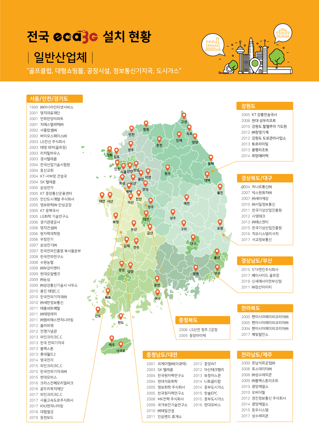
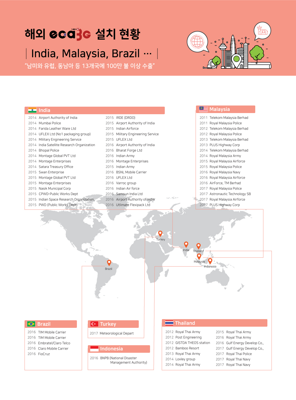
 주요 실적
주요 실적
 낙뢰 피해대책


 139
139