|
|
 |
 |
 |
 |
> 자료실 > 기술자료실 |
 |
|
|
 |
| :: A PROPOSED ROUND ROBIN TEST PLAN |
|
| :: 관리자 |
2007-06-13 16:40:19 ,
조회 :485928 |
| |
::  File download [pdf : 105 KB Download: 9096]
 |
 |
|
|
A PROPOSED ROUND ROBIN
TEST PLAN TO EVALUATE CERTIFICATION
TEST CONDITIONS FOR AIRCRAFT FUEL SYSTEM PIPE COUPLINGS |
| |
J. Anderson Plumer
Lightning Technologies, Inc.
10 Downing Industrial Parkway
Pittsfield, Massachusetts 01201
U.S.A.
japlumer@aol.com |
|
| |
ABSTRACT
There has been increasing interest in the prevention of ignition sources
within fuel tanks due to lightning currents induced in fuel and vent
tubes and other conducting objects within fuel tanks. The SAE fuel
system committee, SAE G-3A (Aerospace Couplings, Fittings, Hose &
Tubing Assemblies) has drafted a proposed environmental test standard
[i] for fuel tube couplers that includes conduction of typical lightning
currents through fuel tube couplings to verify that no arcing occurs
that could ignite flammable fuel vapors. This paper describes a plan
of exploratory tests to determine the conditions under which flames
will and will not propagate to the ends of pipes attached to coupling
specimens of various sizes. An initial series of tests will be conducted
by igniting a hydrogen gas mixture with a small spark at the interior
of tube specimens of various diameters to determine the conditions
that let the flame appear at the open end of the pipe. A second group
of tests will be conducted on couplings attached to short tube ends
and arranged to produce an arc that is exposed to the interior of
the coupling when typical currents are
conducted through the coupling. Such an arc would have a higher energy
dissipation than the 0.2 mJ spark often used to verify ignition sensitivity
of flammable gasses, but most electrical arcs that might occur at
fuel tube ouplings would be significantly hotter, and more incendiary,
than the standard 0.2 mJ spark. Several test laboratories are expected
to conduct the same tests on identical couplings. If these “round
robin” results are consistent, the results will be used to finalize
the fuel tube coupling lightning test standard. |
 |
| |
BACKGROUND
Fuel tube couplings are usually tested for ability to conduct small
amounts of lightning currents without producing arcs or sparks that
can ignite flammable fuel vapors. The most recent standard for these
tests is included in the newly published aircraft lightning test standard
[ii]. In this standard, fuel tube couplers are tested within a chamber
filled with a flammable gas, so that if an incendiary electric arc
or spark occurs at the coupling, it may be identified by the ignition
of the chamber gas. This method of detecting ignition sources has
long been used in fuel system lightning certification tests. Formerly,
mixtures of hydrocarbon gasses such as propane and hexane with air
have been used as the flammable gas. On occasion, evaporated aircraft
fuel vapors have also been used. These gasses, however, do not ignite
reliably at the 0.2 mJ spark energies commonly thought to be capable
of igniting stoichiometric combinations of hydrocarbon vapors and
air. Also, when these gasses do ignite, the resulting
overpressures can damage test chambers. Recently, the hydrocarbon
gasses have been replaced by a mixture of hydrogen, oxygen and argon,
a combination that ignites reliably at 0.2 mJ and does not produce
damaging overpressures [iii]. The hydrogen flames, however, can be
quenched by the presence of cool surfaces such as metal fuel tank
and tube walls. The possibility exists that a flame may be ignited
by an arc on the interior of a coupling and be quenched before reaching
the open end(s) of the coupled tube specimen and, therefore, not be
detected by ignition of the gas surrounding the specimen in the test
chamber. |
| |
OBJECTIVE
The primary objective of the tests described herein is to establish
the diameter and length limitations of the tube ends that can be used
to test fuel tube couplings for ability to conduct lightning currents
without igniting flammable fuel vapors. A secondary objective is to
verify that the test can be applied at different laboratories with
the same test results.
Of particular concern is whether tubes of small diameters will allow
for the propagation of a flame front
sufficient to ensure that an ignition source at the failure will be
detected. SAE committee AE-2 and EUROCAE WG 31 have taken on the task
to perform some experiments within various labs to ensure that the
test article arrangement and lightning test method being proposed
is technically feasible as well as repeatable at different laboratories.
It is expected that this “Round Robin” program will include performance
of the same set of tests on similar
coupling and tube specimens by up to four (4) participating laboratories,
in the US and Europe, and the tests have been termed the “Fuel Coupling
Round Robin Tests”. This is similar to previous round robin test programs
that were sponsored by the SAE and EUROCAE lightning committees to
develop improved methods for high voltage strike attachment testing
of radomes [iv] and high current physical damage testing of aircraft
skin specimens [v]. |
| |
PROPOSED COUPLING LIGHTNING TEST METHOD BY SAE G-3A
SAE G-3A has proposed a standard [i] that defines requirements
for a threadless, flexible, conductive, self-bonding coupling assembly
which, when installed on fixed cavity ferrules, provides a flexible
current carrying connection for joining tubing and components in aircraft
fuel, vent or other systems. The assembled coupling is referred to
as the assembly.
This proposed standard is a departure from prior qualification practices
[vi]. Prior practice sought to validate the coupling design by a sequence
of tests conducted to a set of coupling assemblies. There were multiple
test sequences and a different set of coupling assemblies were tested
with each sequence.
Each of these test sequences challenged a particular design feature
of the coupling. No single coupling was expected to survive all the
required tests.
FAA regulations [vii, viii] together with the increasing use of carbon
fiber reinforced composites (CFC) in fuel tank construction have established
the need for a fuel tube coupling capable of safely conducting amounts
of lightning current that may appear in fuel tubes. A coupling that
required frequent inspection and maintenance to remain lightning capable
for the life of the aircraft would be of little value. |
| |
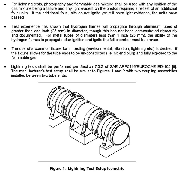
The proposed lightning test is intended to insure that the coupling
assemblies can withstand the predicted
lightning transients over their service life without the creation
of an ignition source under lightning strike conditions.
To ensure that a coupling is lightning capable for the life of the
aircraft, it becomes important to simulate the wear that the coupling
would encounter on the aircraft. The new standard proposed by G-3A
simulates a worse-case wear situation for the installed coupling.
Briefly, the standard proposed by G-3A requires testing of eight coupling
assemblies with end tube assemblies, tube end caps or plugs, coupling
assemblies or similar retaining device and necessary clamp assemblies
for each tube size, material and current level being tested. Four
of the test specimens would be tested un-conditioned and four units
tested after being conditioned by other test conditions described
in the standard. Other features of the G-3A proposal are: |
 |
 |
| |
ROUND ROBIN TESTS
Two tests are proposed.
The first test is called the tube test, and a simple simulation of
an ignition source of typical energy within a tube. This will provide
an initial characterization of flame behavior within thin tubes in
response to a standard ignition source.
The second test, called the coupling test is of a typical non-lightning
rated coupling assembly arranged to produce an expected electric arc
at point contacts at the interior of the coupling interface.
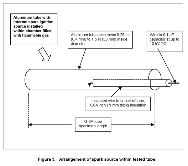
The tube test is to be done by placing an insulated wire
with insulation 0.04 inch (1 mm) thick into the center of the tested
tube that is placed within a chamber filled with flammable gas, so
that a spark can jump from the end of the wire to the interior surface
of the tube. The arrangement is illustrated in Figure 3. The tube
is placed within a gas filled test chamber, so that ignition of the
chamber gas can indicate that a flame propagated to the end(s) of
the pipe.
Other arrangements for the gas filled chamber are to be as described
in Section 7.7.2 of SAE ARP 5416/EUROCAE ED-105 [iii].
Flammable gas. A hydrogen/oxygen/argon mixture (5% Hydrogen, 12% Oxygen
and 83% Argon) is the preferred gas for the ignitable mixture testing.
This mixture has demonstrated greater than 90% probability of ignition
when exposed to a 0.2 mJ voltage spark. Procedures for setting this
gas mixture and verifying the ignition sensitivity of this gas are
given in Section 7.7.2 of SAE ARP 5416/EUROCAE ED-105 [iii]. Variations
in the gas mixture may be tried, as well, if difficulties are found
in propagating the flames to the ends of the tube specimens.
Ignition source. The ignition source for the first test should be
a spark produced by a 0.1 μF energy storage capacitor chargeable to
10 kV. At 10 kV, this will produce a 0.5 J spark. This is higher energy
than the 0.2 mJ spark that is acknowledged to be the minimum spark
energy necessary to ignite hydrocarbon fuel vapors, but more like
the energy associated with an electric arc that might occur at point
contacts within a tube coupling. |
 |
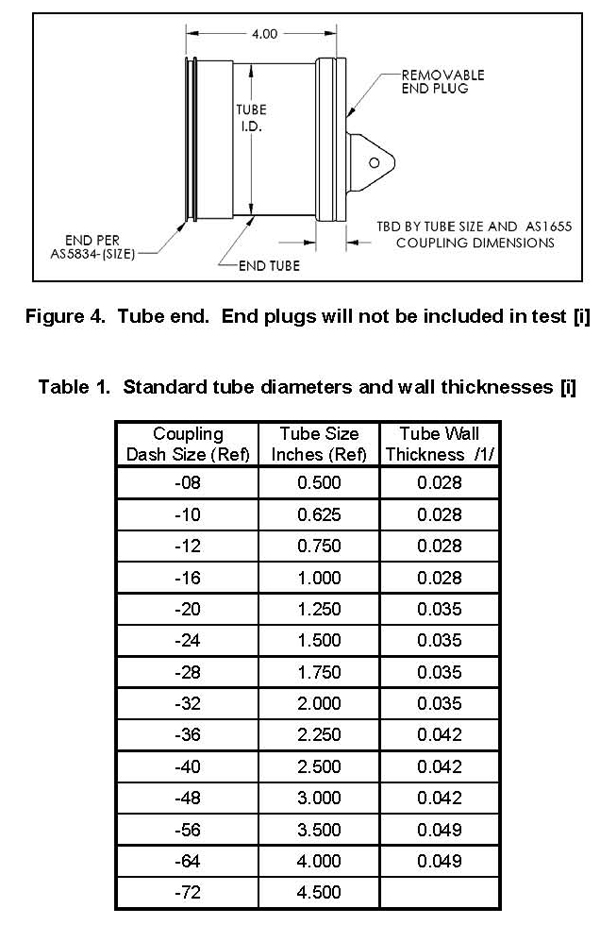
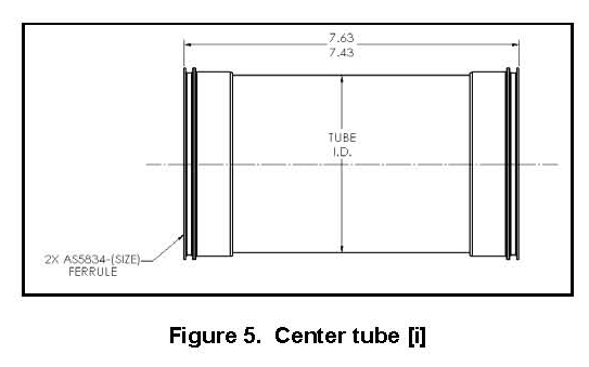
| Tube Dimensions. The standard proposed by SAE G-3A describes tube
ends in Figure 1 of 4 inches (100 mm) long as shown in Figure 4. If
two couplings are tested in series, a center tube 7.43 inches (190
mm) long is to be inserted between the two couplings. Thus, the total
length of the center tube and both tube ends is 15.43 inches (390
mm). It would be advantageous, though not mandatory, to demonstrate
that a flame ignited at only one coupling could propagate past the
other coupling to the opposite tube end, a distance of 7.43 + 4 inches
= 11.43 inches (290 mm). |
 |
 |
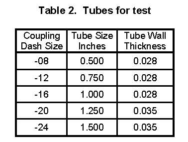
| Experience has shown that flames ignited at the interiors of couplings
on tubes of 1 inch (25 mm) or larger diameter will propagate out of
the tube ends and ignite the chamber gas. Thus, from Table 1, tubes
of 1 inch and smaller diameters should be tested, although the proposed
G-3A standard addresses tubes down to 0.5 inch (23 mm) diameter. Whereas
tubes of smaller diameters are sometimes found in aircraft fuel tanks,
they are rarely used for fuel vent applications (where the interiors
would contain vapors and not liquid fuel). Thus, the tube sizes shown
in Table 2 are recommended for these round robin tests. |
| |
 |
The length of all tube specimens can be 15.43 inches
(390 mm) so that by positioning the wire at 4 inches (100 mm) and
again at 7.43 inches (190 mm) from an open tube end, both of the ignition
conditions described above can be evaluated in the same specimen.
It is not expected that tube wall thickness will influence the round
robin test results, however, it is advisable to use the thicknesses
listed in Table 2 since they are standard thicknesses, and most likely
to be available.
Other items. The tests
should be conducted under laboratory ambient atmospheric conditions
similar to the conditions in which the couplings will be tested in
accordance with the G-3A proposed standard.
Tube
test procedures. Tests should begin with the largest diameter
tube specimen listed in Table 2, and continued with tests of smaller
diameter tubes until it is no longer possible for flames ignited inside
the tube to ignite the chamber gas.
The standard proposed by G-3A calls for three tests to be applied
to each coupling specimen with test current in each direction for
a total of six tests. Thus, it is necessary that ignition sources
inside the tubes produce flames that will reach the chamber gas in
six out of six ignitions.
The round robin tests should demonstrate this result by applying six
sparks within each of the tested tubes. No tube current, of course,
is needed for these tube tests.
The procedures for preparing the chamber and flammable gas are to
be as described in Section 7.7.2 of SAE ARP5416/EUROCAE ED-105 [iii]
and will not be repeated here.
|
The tests should begin with the wire end 4 inches (100 mm) from
an open end of the tube. An effort should be made to have the interior
end of the wire insulation in contact with the tube, so that there
will be a ~1 mm gap between the copper wire and the tube surface.
The tests will be conducted by raising the voltage on the energy storage
capacitor until a spark is formed
between the end of the wire and the internal surface of the tube.
If the wire insulation is touching the tube interior surface, the
insulation will spark at about 5 kV. If the wire is not touching the
tube surface, higher voltage will be required. The voltages at which
sparks occur should be recorded.
Note that no effort should be spent attempting to create a 0.2 mJ
spark inside the tube. This would be a formidable task given the influence
of stray capacitance and spark length on this standard.
If all of the 4-inch (100 mm) tests have been completed successfully,
the test series should be repeated with the wire end 7.43 inches (190
mm) from one end of the tube.
The coupling tests are
similar to the tube tests, but provide a more realistic ignition source,
this being an electric arc (sometimes called a ‘thermal spark’) instead
of a spark (sometimes called a ‘voltage spark’). Arcs are produced
by current across inadequate electrode contacts, whereas sparks are
produced by voltages that ionize air between electrodes not in contact.
Since the standard proposed by SAE G-3A applies to couplings that
have greater potential for arcs than for sparks, it is important to
try the proposed coupling tests with more realistic ignition sources.
Since couplings may also produce arcs at exterior surfaces, round
robin tests only of tubes with couplings would probably be inconclusive.
The major difference between the tube tests and the coupling tests
is that the ignition sources are to be produced in non-lightning rated
couplings by injection of current through the coupling. A wire to
the interior of the specimen with voltage applied will not be used.
Other aspects of the tests are the same as for the tube tests. Further
details are as follows:
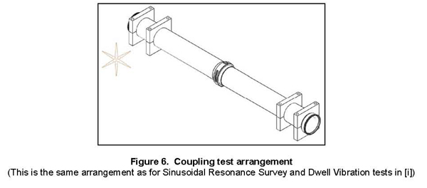
Test specimens: Type AS1650 couplers [vi] that do not have internal
electrical bonding provisions or lightning current carrying capability
ratings should be tested. The arrangement of Figure 2b of the proposed
SAE G-3A standard [i], wherein two couplings are tested in series,
in the same center and end tubes should not be used since this will
produce confusing results. Instead, a single coupling between two
11.43 inch (290 mm) tube ends should be tested. This arrangement is
as shown in Figure 6. The tube ends are supported by one or two clamps
made of non-conducting material, as necessary, to position the tube
ends and coupling to obtain the desired point contact of the ferrules.
|
 |
| |
Couplings commensurate with the tube sizes in Table 2 should be
tested. Only one coupling in one set of
tube ends need be tested, unless the tests produce welding or other
damage that prevents internal arcing. As recommended in the standard
proposed by SAEG-3A [i], the tube ends should be positioned 3.5 degrees
apart, as necessary to produce a point contact between ferrules on
the interior of the coupling.
Test current: The test current should have the waveform of Current
Component B as defined in SAE ARP 5412/EUROCAE ED-84 [ix] as recommended
in the proposed standard [i] and Section 7.3.3 of SAE ARP5416 [ii].
This waveform is typical of lightning currents that re-distribute
to metal conductors within both metal and CFC fuel tanks.
The Current Component B waveform also represents the longer duration
components of the external lightning environment that couple most
efficiently to conductors inside of fuel tanks and other aircraft
structures without apertures through which external magnetic fields
may penetrate. The Current Component B waveform is shown in Figure
7. |
 |
From experience, it has been shown that current amplitudes of 500
A have produced internal arcing capable of reliably igniting flammable
gasses within the tubes.
Currents in fuel tubes have been reported [x] to range between 10s
and 100s of amperes in most installations. Some tubes that are installed
within fuel tanks made of CFC, or attached to pumps installed in exterior
skins within lightning strike zones, have experienced 1000s of amperes
of current.
Photography: The Hydrogen gas does not emit visible light during the
burn which allows the simultaneous use of photography and flammable
gas to detect arc or spark ignition sources. For the coupling tests,
it is recommended that photography be used together with the hydrogen
gas mixture so that arc or spark ignition sources on the exterior
of the coupling specimen can be detected. Flames ignited by exterior
ignition sources should be recorded, but these do not contribute to
the desired test results. If ignition sources appear on the exterior
of the coupling, the coupling should be rearranged to eliminate those
sources. Only ignitions originating inside the tube are to be counted
for this round robin test series.
Ability of flames, once ignited, to propagate through tubes is not
related closely to the energy dissipated by the ignition source. An
exception to this is when there are several, simultaneously-occurring
ignition sources within the same tube, in which event flames may quickly
become explosions and propagate with sonic velocities. This is why
only one coupling should be included in the tube test specimen shown
in Figure 6.
A successful test result is one in which the ignition within the tube
has ignited the chamber gas.
The six tests described above should be applied to each tube and coupling
diameter specimen listed in Table 2 until flames ignited inside the
tube no longer ignite the chamber gas. Six tests are proposed since
that is the number included in the standard proposed by SAE G-3A.
In that proposal, three tests are to be applied with the test current
‘positive’ (i.e. in one direction), and the other three tests are
to be applied with ‘negative’ (i.e. the current in the other direction).
Since the possible contacting surfaces within the coupling are the
same on both sides, the direction of current should have no influence
on test results. Thus, the plan to apply six tests is simply to remain
numerically consistent with the G-3A proposal. |
| |
| Documentation: The round robin reports should provide details of
all test specimens, test conditions and test results in sufficient
detail that they can be combined with results of tests at other laboratories
for presentation to the EUROCAE and SAE lightning committees who will
review the results and provide recommendations to the SAE G-3A committee
for inclusion in the final lightning capable coupling standard. |
| |
REFERENCES
i. Proposed Draft Aerospace Standard, SAE AS5830 “Coupling Asembly,
Threadless, Flexible, Fixed Cavity, Lightning Capable, Self Bonding,
Procurement Specification”
ii. SAE ARP5416/ EUROCAE ED-105 “Aircraft Lightning Test Methods”
Section 7.3.3, 2005-03
iii. SAE ARP5416/ EUROCAE ED-105 “Aircraft Lightning Test Methods”
Section 7.7.2, 2005-03
iv. Pryzby, J.E., Dargi, M.M. “Evaluation Of Proposed Method For High
Current Testing Of Aircraft Optical Transparencies” Lightning Technologies,
Inc. Report LT-00-1766, 4 May 2000
v. Hall, A. L. “Summary Of Robin Test Results To Evaluate New Radome
Test Method And Procedures” Lightning technologies, Inc. Report LT-01-1978,
29 November 2001
vi. SAE AS1650 REV A “Coupling Assembly, Threadless, Flexible, Fixed
Cavity, Self-Bonding, Procurement Specification” Society of Automotive
Engineers, Inc. May, 1999
vii. 14CFR25/23/27/29.954 “Fuel System Lightning Protection” Federal
Aviation Administration
viii. 14CFR25.981 “Lightning protection” Federal Aviation Administration
ix. SAE ARP5412, 11/99, 3/05/ EUROCAE ED-84, 8/97; A1, 9/99; A2, 5/01
“Aircraft Lightning Environment and Related Test Waveforms (Standard)”
x. Crouch, K.E., Bootsma, P.H. “Lightning Current Levels in Aircraft
Fuel System Plumbing” 01ICOLSE-68 |
|
|
|
|
|
| |
|
::
File download [pdf : 105 KB Download: 9096] |
|
|
|
|
 139 139 |
|
|
| Copyright © 1998-2015 by Ground.Co., Ltd., All rights reserved. |
|
|
 |
|
|
 eca3G 성능인증(EPC)획득
 낙뢰방호 현장설계모음
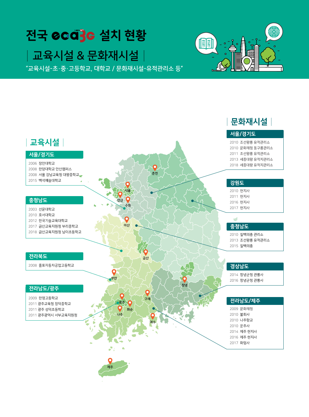
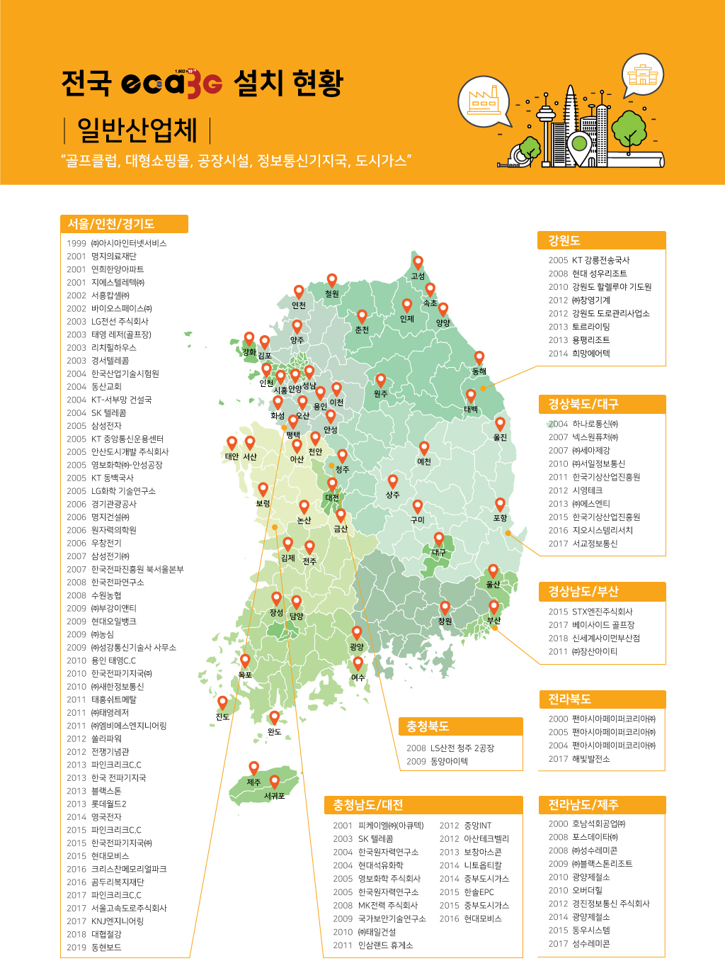
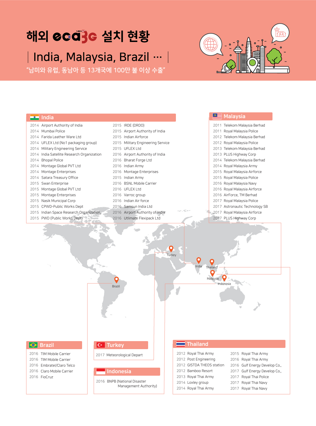
 주요 실적
주요 실적
 낙뢰 피해대책


