|
|
 |
 |
 |
 |
> 자료실 > 기술자료실 |
 |
|
|
 |
| :: A PROPOSED ADDITION TO LIGHTNING ENVIRONMENT |
|
| :: 관리자 |
2007-06-13 16:41:10 ,
조회 :484580 |
| |
::  File download [pdf : 228 KB Download: 9418]
 |
 |
|
|
A PROPOSED ADDITION
TO THE LIGHTNING ENVIRONMENT STANDARDS
APPLICABLE TO AIRCRAFT TO ACCOUNT FOR EFFECTS OF POSITIVE
LIGHTNING STROKES OF LONG DURATION AND MODERATE INTENSITY |
| |
J. Anderson Plumer
Lightning Technologies, Inc.
10 Downing Industrial Parkway
Pittsfield, Massachusetts 01201
U.S.A.
japlumer@aol.com |
|
| |
ABSTRACT
Lightning strike incidents to commercial and military aircraft and
helicopters have produced damage unlike what is usually inflicted
by laboratory tests conducted in accordance with the aircraft lightning
environment defined in present aircraft lightning environment standards
including SAE ARP5412 and EUROCAE ED 81 and US Military Standard 464A
(and predecessor standards dating back to 1970).
These standards define a first stroke current of 200 kA peak amplitude
and overall time duration of 500 μs followed by intermediate and continuing
currents whose amplitudes do not exceed 4 kA. There is no recognition
of the possibility of lightning stroke currents of higher amplitude
than 200 KA or, more likely, of lower than 200 kA amplitude, but of
longer time duration than 500 μs. The physical damage effects that
have prompted this review appear to have resulted from lightning stroke
currents that have long durations and moderate to severe amplitudes,
but not the fast rates of rise (di/dt) usually associated with lightning
stroke currents especially those that lower negative charge to earth.
A proposal is made to add to the present aircraft lightning standards
a current component that represents a long duration stroke current
of moderate amplitude. It is suggested that this proposal be taken
up by the committees responsible for updating aircraft lightning standards:
SAE AE2 and EUROCAE WG31. This proposal might be extended to incorporate
a higher amplitude version of this current component to account also
for some effects that can only be attributable to strokes of very
high action integrals, but such an extension is not discussed in this
paper. |

|
| |
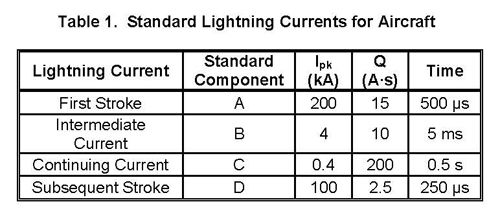
PRESENT AIRCRAFT LIGHTNING STANDARDS
The lightning current components applicable to aircraft lightning
protection design and certification are published in SAE and EUROCAE
[i,ii] include synthesized current waveforms representing several
aspects of the cloud to earth lightning flash currents as listed in
Table 1. |
 |
These standard waveforms have evolved through early US and European
standards originating in the 1960’s to include the current components
listed above and more fully defined in [i,ii]. The present standards
were last agreed upon among aircraft lightning specialists in the
US and Europe in the mid 1980s. The origins of these standard current
components come from several databases containing measurements of
cloud-to-earth lightning flash currents [iii,iv]. Examples of negative
stroke currents contained in one of the databases are shown in Figure
1.
Unlike electromagnetic compatibility (EMC) environments that prescribe
a continuous frequency and
corresponding amplitude environment, the lightning environment has
been confined to a group of time domain pulses with no information
between the specific characteristics of these pulses which represent
stroke, intermediate, and continuing currents.
Statistics show that negative first stroke amplitudes rarely exceed
100 kA and have decay time durations within the 500 μs decay times
(to ~5%) assumed for standard first stroke. The 200 kA peak amplitude
assigned to the 500 ms stroke, called Component A, was chosen to reflect
positive polarity strokes though statistics [i,ii] indicate that 5%
of positive strokes reach peaks of up to 250 kA. |
| |
POSITIVE LIGHTNING STROKES
The time durations of positive lightning strokes are widely
believed to extend to several ms, so that larger amounts of charge
are transferred by the positive stroke currents. A recent summary
of positive lightning flash Characteristics, compiled by the US and
European lightning standards committees, is found in [i,ii] and reproduced
here as Table 2. |
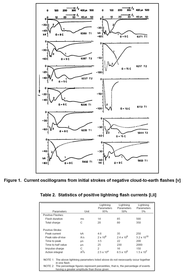 |
It will be noted that the decay times to 50% at the 5% (exceeding)
severity level is about 2 ms which is over 20 times the decay time
assigned to the first stroke component in the present aircraft standard.
The impulse charge (transferred by the stroke alone) of 150 A·s (coulombs)
is also much greater than
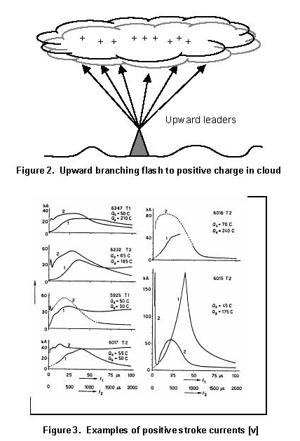
delivered by Component A. Oscillographic records of positive lightning
strokes to earth are rare; the most important data being that published
on 26 positive stroke currents by Berger and Vogelsanger [v,vi], examples
of which are shown in Figure 3. Rakov, in his review of positive lightning
stroke characteristics
[vii], has noted that a reliable distribution of positive lightning
stroke peak currents is not available, and that positive stroke currents
from leaders that originate in the cloud (like most negative leaders)
are of much shorter duration (100s of μs) than are stroke currents
resulting from leaders originating from tall objects on the ground.
The latter often result in multiple upward leaders, each neutralizing
positive charge in a different region within the cloud above. It is
questionable, then, whether an aircraft struck by such a flash would
experience all of the stroke current, since some would likely be transferred
by leaders not attaching to the aircraft. Such a flash is illustrated
in Figure 2. But, there is no assurance that an airplane would not
be a conduit for all upward leaders and stroke currents which may
branch upward from an aircraft that first encountered only one upward
leader. |
 |
| |
AIRCRAFT EXPERIENCE
Several in-flight lightning strike incidents have shown physical
damage that is indicative of moderate to severe stroke currents with
time durations to several milliseconds or even 10s of milliseconds.
The physical damage appears to have resulted from unusually strong
magnetic forces among conductors including bond straps, forces that
have been strong as well as persistent, and these incidents have also
left evidence of large charge transfers well in excess of those assigned
to the presently defined intermediate and continuing currents Components
B and C*.
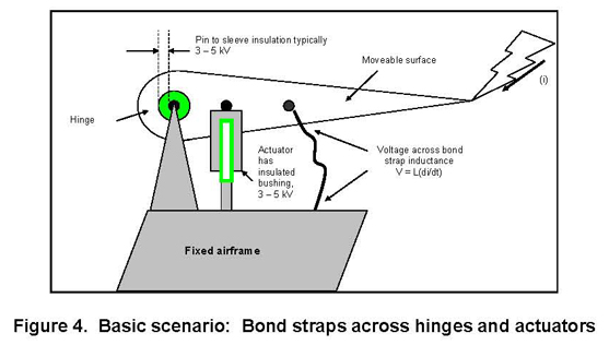
One of the incidents is described briefly here, together with an assessment
of what the nature of the lightning current may have been. The basic
scenario, which has been repeated in several recent incidents involves
the effects of severe lightning currents in bond straps across parallel
paths not intended for lightning currents as shown simply in Figure
4. |
 |
A mid-sized aircraft was approaching an airport when it received
a lightning strike that initially entered one of the horizontal stabilizer
tips and initially exited from the lower surface of the nose.
The final entry location was the aft end of the fuselage, and the
final exit location was also at the same horizontal stabilizer tip.
This is a very typical lightning strike scenario, particularly when
the aircraft has encountered a cloud-to-earth flash as can happen
when the altitude was between 12,000-14,000 ft. The airspeed was reported
to be 280 knots when the lightning strike occurred. Significantly,
the pilots did not report a loud noise associated with this strike.
The horizontal stabilizer was attached to the aircraft by a mechanical
hinge and a hydraulic trim actuator.
Two parallel braided copper bond straps provided paths for lightning
currents to flow between stabilizer and fixed airframe.
This aircraft is ~30 m long and the lightning seems to have been mostly
done by the time of the last visible lightning attachment point which
was on the tail of the fuselage. At 280 knots, this would imply a
typical flash time duration of ~300 ms. The US National Lightning
Detection Network (NLDN) reported a cloud-to-earth flash of positive
polarity at about the same time and place as the aircraft was struck.
A hypothetical positive lightning flash that may have caused the observed
damage is shown in Figure 5.
It includes one long duration stroke current followed by continuing
current. Its peak stroke current is 30 kA and total charge transfer
is 220 coulombs (A·s). Its total time duration is ~300 ms. |
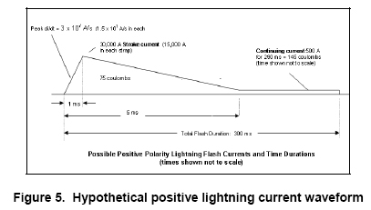 |
The stroke current of Figure 5 has an average rate of rise of 3
x 107 A/s. It may be presumed that the peak di/dt for such as stroke
would be about one order of magnitude greater or 3 x 10⁸ A/s (not
unreasonable when compared with the ranges in Table 1), thus 1.5 x
108 A/s in each of the two parallel bond straps. If the inductance
of each bond strap is assumed to be 0.25 μH (a typical value for a
short bond strap), the voltage in the loop between each bond strap
and the nearest structural element (i.e. an hydraulic actuator piston)
would be 37.5 volts which is not enough to cause sparkover of the
bushing insulation surrounding the hydraulic actuator piston. Sparkover
voltages of insulation such as this are typically in the 3,000-5,000
volt range (not adjusted for reduced pressures at flight altitudes).
Inspection of the aircraft after landing showed no evidence of sparkover
of a hydraulic actuator bushing or of the lubricating sleeves surrounding
the hinge pins, either of which would have provided additional paths
for
lightning currents to transfer from the moveable surface to the aircraft
fixed structure. Visual inspection of the aircraft after landing indicated
more than 200 coulombs worth of erosion effects on the fuselage belly
where the flash currents entered the airplane, and a similar amount
of erosion at the static wick base on the horizontal stabilizer tip
where the flash currents exited from the aircraft. The terms “entry”
and “exit” have nothing to do with the physical effects of lightning
attachment. The effects of charge entering or exiting a location on
the same type of structural surface are nearly the same. |
| |
Significant effects: Two bond straps, which provide
paths for lightning currents between the horizontal tail surfaces
and the vertical fin, were broken or pulled away from their lugs,
but they had not been melted or vaporized. These bond straps bypass
hydraulic actuators that have non-conducting cylinder bushings.
As noted above, there was no evidence of surface flashover across
the bushing insulation which would have happened had there been the
usual fast rate of rise (di/dt) of negative stroke starting to flow
in the bond strap inductances.
Instead, it is evident that all this stroke current flowed in the
failed bond straps or in the electric arcs that followed the broken
straps. |
| |
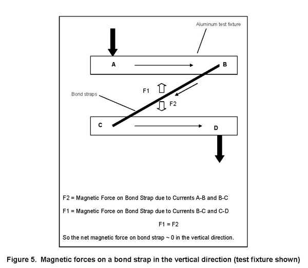
Mechanical forces on the bond straps: During lightning current flow
in the two parallel bond straps, each approximately 15 cm long and
approximately 15 cm apart, there would have been electromotive forces
pulling on these straps in the vertical and horizontal directions.
These forces attract the current carrying conductors together if the
currents are in the same direction as in the two bond straps. Currents
in opposite directions produce repelling forces.
Some forces in both directions would have existed on these straps,
and would have canceled at the straps as illustrated in Figure 5,
but the strongest forces would have been attraction between the two
that were parallel to each other. The expression for these forces
is: |
| dP/dL = (2μI1I2)/D (Newtons/m) |
| Where I1 and I2 are the currents in the two bond straps (assumed
to be 15,000 A in this example) and D is the distance between the
straps (m), assumed to be 0.15 m in this example. μ is the permeability
of free space (4π x 10-7 H/m). P is pressure (Newtons) and L is the
unit of conductor length (m). |
 |
| Nevertheless, strong forces existed in the horizontal direction
to pull the straps out of their connection lugs. The origin of these
forces is evident in the top view of the same bond strap installation
as shown in Figure 6. |
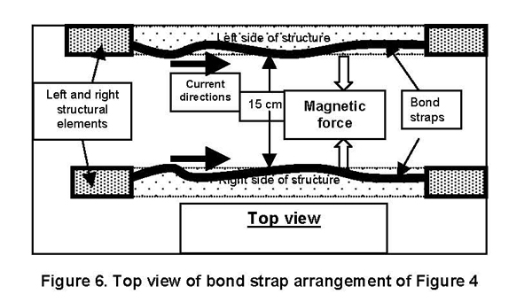 |
The resulting magnetic forces under the hypothetical conditions
described above are ~128 lbs. acting on each parallel strap in the
direction of the other strap. The magnetic force amplitude is due
to the peak current, but not the rate of change of current. However,
the effect of this force on the bond strap (and associated crimped-on
lugs, brackets, rivets) would certainly be influenced by the time
duration of this force which, in the hypothesized lightning flash
described in Figure 5, is considerably longer (5 ms) than the time
duration assigned to the present standard lightning stroke (Component
A, ~0.5 ms).
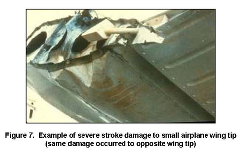
Other flight lightning strike incidents have caused similar effects
including excessive melting and deformations of metals, breaking of
bond straps, and burning of materials which are not characteristic
of effects of the standard lightning environment (Components A, B,
C and D). An example is shown in Figure 7. |
| |
 |
There have not usually been indirect effects associated with the
same lightning strike incidents indicating
that the rates of rise (di/dt) of the lightning stroke currents have
not been unusually high.
There is some recorded evidence that the lightning strikes that have
caused this unusual damage have been “positive” cloud-to-earth lightning
strikes that, in fact, raise negative charge from the earth to the
cloud. |
| |
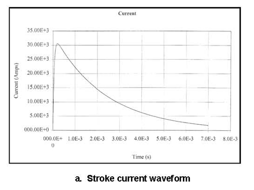
PROPOSAL TO ADDRESS LONG DURATION STROKE CURRENT EFFECTS
An addition, such as the combined long duration stroke and
continuing current of Figure 5, could be added to the family of standard
lightning current components as shown in Figure 8. Such an environment,
if applicable when the bond strap installation described above was
designed, might have prompted a design modification that would have
prevented the damage that occurred during this strike.
There are numerous combinations of stroke current amplitude and time
duration that would explain the effects observed following the strike
incidents described above.
There is some recorded evidence that the lightning strikes that have
caused this unusual damage have been “positive” cloud-to-earth lightning
strikes that, in fact, raise negative charge from the earth to the
cloud. |
 |
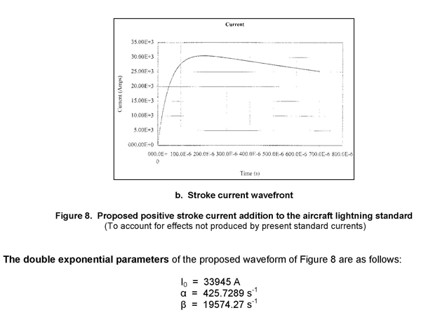 |
The rise time to crest is 200 μs and the decay time to ½ peak amplitude
is about 2 ms. The total charge transfer (to 7 ms) is 74 coulombs.
The action integral (specific energy) is 1.26 x 10⁶ A2s (also J/ohm).
The rise and decay time parameters are (coincidentally) the same as
those shown for the 5% severity (95% are less severe) column for positive
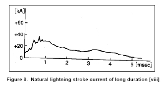
strokes in Table 2. They are, coincidentally, also similar to the
positive polarity lightning stroke current oscillogram that was presented
to the SAE and EUROCAE lightning committees by observers in Japan
[viii] and shown in Figure 9. It will also be noted that the double
exponential waveshape parameters for standard Component B (α = 700
s-1, β = 2000 s-1) are similar to those proposed above, except that
the Component B waveform rises to crest in approximately 1 ms, somewhat
long for a stroke current.
The amplitude of 30 kA will produce magnetic forces among bond straps,
etc. sufficient to pull such straps out of lugs and terminals as shown
earlier. It is noteworthy that the bond strap braids themselves have
not been vaporized during the reported strike incidents. A copper
strap of equivalent cross section of an American Wire Guide (AWG)
No. 8 conductor will experience a temperature rise of ~110ºC and the
temperature of an AWG No. 10 conductor will increase by 380º C due
to a stroke current with action integral of 1.26 x 10⁶ A2s. This is
not sufficient to melt or vaporize these copper conductors, but it
may weaken terminal lugs and allow the magnetic forces to pull the
straps free. |
 |
The rate of rise (di/dt) of the proposed
waveform is 6.5 x 10⁸ A/s at T = O+. This produces 650 volts across
an inductance of 1 μH and only 163 V across the bond strap inductance
of 0.25 μH which was assumed in the assessment of the bond strap damage
described earlier in this paper. This peak di/dt is between the 50%
and 5% values of peak di/dt in Table 2. There is no intent to assign
a high value of di/dt to this new waveform, since high di/dt values
are already assigned to Components A, D and H in the existing standard.
Conversely, it is intended to assign a di/dt that will not produce
sparkovers of traditional aircraft hardware insulation, such as control
surface hinges, actuators and other small gaps among conducting structures,
while representing typical positive stroke currents of moderate intensity.
The peak di/dt associated with the waveform of Figure 8 appears to
meet this intent.
The decay time of 2 ms
to 50% and about 5 ms to 10% (the approximate amplitude of standard
Component B) appears representative of +CG strokes, as indicated by
Berger’s oscillograms of Figure 3, and the physical evidence of substantial
current spread along significant percentages of the aircraft length
in some of the strike incidents giving rise to this proposal.
The impulse charge of 75 coulombs (A·s) is also
within the range of 50% and 5% severities listed in Table 2 and observed
on aircraft that appear to have encountered +CG stroke currents. Total
charge transfers of 80 and 350 coulombs for the 50% and 5% severities,
respectively, include the charge transferred by the continuing currents
that usually follow the stroke currents in the same channel. For design
and test purposes, the proposed waveform of Figure 8 would be followed
by an appropriate amount of continuing current, probably Component
C, so that the total charge transferred would be ~275 coulombs.
Applications of the proposed waveform: The primary
purpose of the proposed waveform is for design of protection against
effects of the lightning environment not represented by the present
standards.
Laboratory tests with the proposed waveform to evaluate or verify
designs, using common capacitor discharge circuits, will not be possible
with most impulse generators presently available for aircraft lightning
testing. It is easy to make high amplitude currents of short duration
and low amplitude currents of long duration (i.e. the standard Components
A and C), but more difficult to make intermediate combinations. The
waveform of Figure 8 was computed from a 1,200 μF capacitor bank charged
to 65 kV and discharged through a 2-ohm resistance and 100 μH inductance.
The energy stored in the 1200 μF capacitor bank is 2.5 megajoules.
Other combinations of R, L and C can produce similar waveshapes, but
the 75 coulomb impulse charge
necessitates that the product of C and V be 75. Since it is impractical
to operate most banks of paralleled capacitors above 100 kV, a large
amount of capacitance will be needed. Inductive energy storage might
be an option, where 30 kA current is first established in a C-L circuit
and then commuted to an L-R circuit.
The energy stored in rotating machinery may also be used to make this
waveform, i.e. being similar to that driving short circuit currents
produced for tests of switchgear in power industry laboratories.
Assessments of the ways the proposed current divides and redistributes
among aircraft structural elements and internal conductors, such as
fuel tubes and flight control cables, can, of course, be done by tests
at lower amplitudes with results extrapolated to establish full threat
levels throughout an airframe.
Once the distributions are known, it will be easier to test coupon
specimens at proportionately lower, more practical currents. The proposed
waveform fits within the description of Component B which is routinely
produced in most aircraft test laboratories.
Finally, most of the physical effects, such as temperature rises and
magnetic force effects of the proposed current waveform on aircraft
structural materials and other conductors, like bond straps, can be
computed. The possibilities of arcing at structural interfaces and
tube couplings cannot be evaluated by computation, but these can be
usually evaluated by tests at the component level.
One unique current component, like the other current components in
the standard lightning environment, may not be what is needed to deal
with the effects of the lightning current environments that have been
causing effects such as the dual bond strap failure noted above. It
is possible that ranges of amplitudes 11 and time durations of stroke
currents should be given in the standards as design parameters, though
this complicates the job of the designer. |
Positive CG flash statistics: There have not been
many oscillographic measurements of +CG stroke currents. A review
of statistics of positive cloud to earth (+CG) lightning stroke parameters,
deduced from far field signatures of CG flashes by the US National
Lightning Detection Network (NLDN), shows that about 10% of all CG
flashes in the US are +CG flashes and the mean amplitude of the stroke
currents in these flashes is between 25 kA and 40 kA, depending on
location and time of year.
For example, cloud-to-ground lightning data have been analyzed by
Orville and Huffines [ix] for the years
1995-97 for the contiguous United States for total flashes, the percentages
of +CG flashes, peak currents for negative and positive flashes. The
authors examined a total of 75.8 million flashes. The highest flash
densities were found in Louisiana and Florida, typically exceeding
11 flashes km?2. Positive flash densities reported in [ix] exceeded
1.1 flashes km?2 in these states, and parts of Tennessee, Mississippi
and Kentucky.
The monthly percentage of +CG lightning reported in [ix] ranged from
6.5% (July 1995) to 24.5% (January 1996). The annual percentage of
positive lightning was 9.3% (1995), 10.2% (1996), and 10.1% (1997).
Areas of +CG occurrence greater than 25% existed from the Canadian
border to as far south as Kansas, and along the West Coast, and in
Maine.
The median positive peak currents were highest in February (25 kA)
and decreased to a minimum in July (15 kA). Median positive peak currents
exceeded 40 kA in the upper Midwest, but were less than 10 kA in Louisiana
and Florida. Thus the proposed waveform of Figure 8 is apparently
near the median for +CG strokes where the range of amplitudes has
been the highest in the US.
Lyons, Uliasz and Nelson [x] studied the same data source for statistics
of +CG flashes in the summer months that exceed 75 kA. They termed
these “LPC+CG” flashes and found that 13% of all CG flashes exceeding
75 kA were LPC+CG and that almost 70% of these occurred in the central
US (30-50ºN, 88-110ºW). They also found that the percentage of all
flashes that were positive approached 30% in the central US and 4.5%
for the remainder of the country.
Statistics of +CG stroke current amplitudes in other parts of the
world were not obtained for reference in this paper. There is evidence,
from several aircraft lightning strike incidents, that high intensity
+CG strokes have occurred in northern Europe and in Japan. The damage
from some of these in-flight strike incidents indicated action integrals
well in excess of the 1.26 x 10⁶ A2s associated with the proposed
stroke waveform. Thus, at the proposed 30 kA, the waveform does not
account for the high action integral effects. |
| |
Table 2 indicates that 5% of all +CG stroke currents have action
integrals exceeding 15 x 106 A2s. This
value could be reached if the amplitude of the proposed stroke current
is increased to ~100 kA. |
| |
Thus, the incidence of positive lightning strokes of moderate intensity
would seem significant enough to
prompt consideration of this part of the lightning environment in
the standards applicable to aircraft. |
| |
REFERENCES
i. EUROCAE ED-84, 8/97; A1, 9/99; A2, 5/01 “Aircraft Lightning Environment
and Related Test Waveforms (Standard)”
ii. SAE ARP5412, 11/99, 3/05 “Aircraft Lightning Environment and Related
Test Waveforms (Standard)”
iii. R. B. Anderson and A. J. Eriksson “Lightning Parameters for Engineering
Applications“ Elektra, Vol. 69, pp. 65-102
iv. N. Cianos and E. T. Pierce “A Ground Lightning Environment for
Engineering Use” Technical Report 1 prepared by Stanford Research
Institute for McDonnell Douglas Astronautics Corporation, August 1972
v. K. Berger and E. Vogelsanger “Photographische Blitzuntersuchungen
der Jahre 1955 ? 1965 auf dem Monte SanSalvatore” Bulletin des Schweizerischen
Electrotechnischen Vereins, 14 (July 9, 1966) pp. 599- 620
vi. K. Berger, “Novel Observations on Lightning Discharges: Results
of Research on Monte San Salvatore” Journal of the Franklin Institute,
Vol. 283, 6 June, 1967, pp. 478-525
vii. V. A Rakov “Positive and Bipolar lightning Discharges: A Review“,
Proc. 25th Int. Conf. on Lightning Protection, 2000
viii. Data provided by Prof. S. Yokoyama, Kyushu University, Japan
ix. R. E. Orville, G. R. Huffines ”Lightning Ground Flash Measurements
over the Contiguous United States: 1995-97”, Monthly Weather Review
1999, 127: 2693-2703
x. W. A. Lyons, M. Uliasz and T. E. Nelson “Large Peak Current Cloud-to-Ground
Lightning Flashes During the Summer Months in the Contiguous United
States” FMA Research, Inc., Ft. Collins, Colorado |
|
|
|
|
|
| |
|
::
File download [pdf : 228 KB Download: 9418] |
|
|
|
|
 139 139 |
|
|
| Copyright © 1998-2015 by Ground.Co., Ltd., All rights reserved. |
|
|
 |
|
|
 eca3G 성능인증(EPC)획득
 낙뢰방호 현장설계모음
 주요 실적
주요 실적
 낙뢰 피해대책


